Elevated working platform and related methods

a working platform and platform technology, applied in ladders, building construction, construction, etc., can solve the problems of unstable ladders, time-consuming and laborious, and workers' inefficiency in completing tasks, so as to achieve safe working environment and large surface area

Active Publication Date: 2017-05-30
LITTLE GIANT LADDER SYST LLC
View PDF24 Cites 17 Cited by
  • Summary
  • Abstract
  • Description
  • Claims
  • Application Information

AI Technical Summary

Benefits of technology

[0008]In accordance with the present invention, various embodiments of an elevated work platform, as well as associated methods, are provided. The elevated platform may provide a relatively large surface area for a user to stand on while working at an elevated height while also providing a safe working environment without the need to continually tie-off or wear a harness during the use of the apparatus.
[0015]In one embodiment, a bather member may be positioned on an interior surface of the outer rail assembly at a location adjacent the at least one adjusting mechanism. The barrier member may be configured and located to prevent potential injury to a user's hands or fingers.

Problems solved by technology

However, breaking down or disassembling such a configuration, moving all of the components and then setting them up again can be time consuming and require considerable effort.
Additionally, there are typically no safety constraints used in such a configuration, making the use of planks a potential safety concern.
At a minimum, users of a ladder will typically find that such requirements take additional time, making the worker less efficient at completing their task, even if they are safer while working.
Climbing beyond the highest recommended rung can make the ladder unstable.
Additionally, the user may become unstable when climbing beyond a recommended height because, for example, they may not have any additional structure to lean against or grasp with a free hand while standing at or near the very top of the ladder.

Method used


Image

  • Elevated working platform and related methods
  • Elevated working platform and related methods
  • Elevated working platform and related methods

Examples


Embodiment Construction

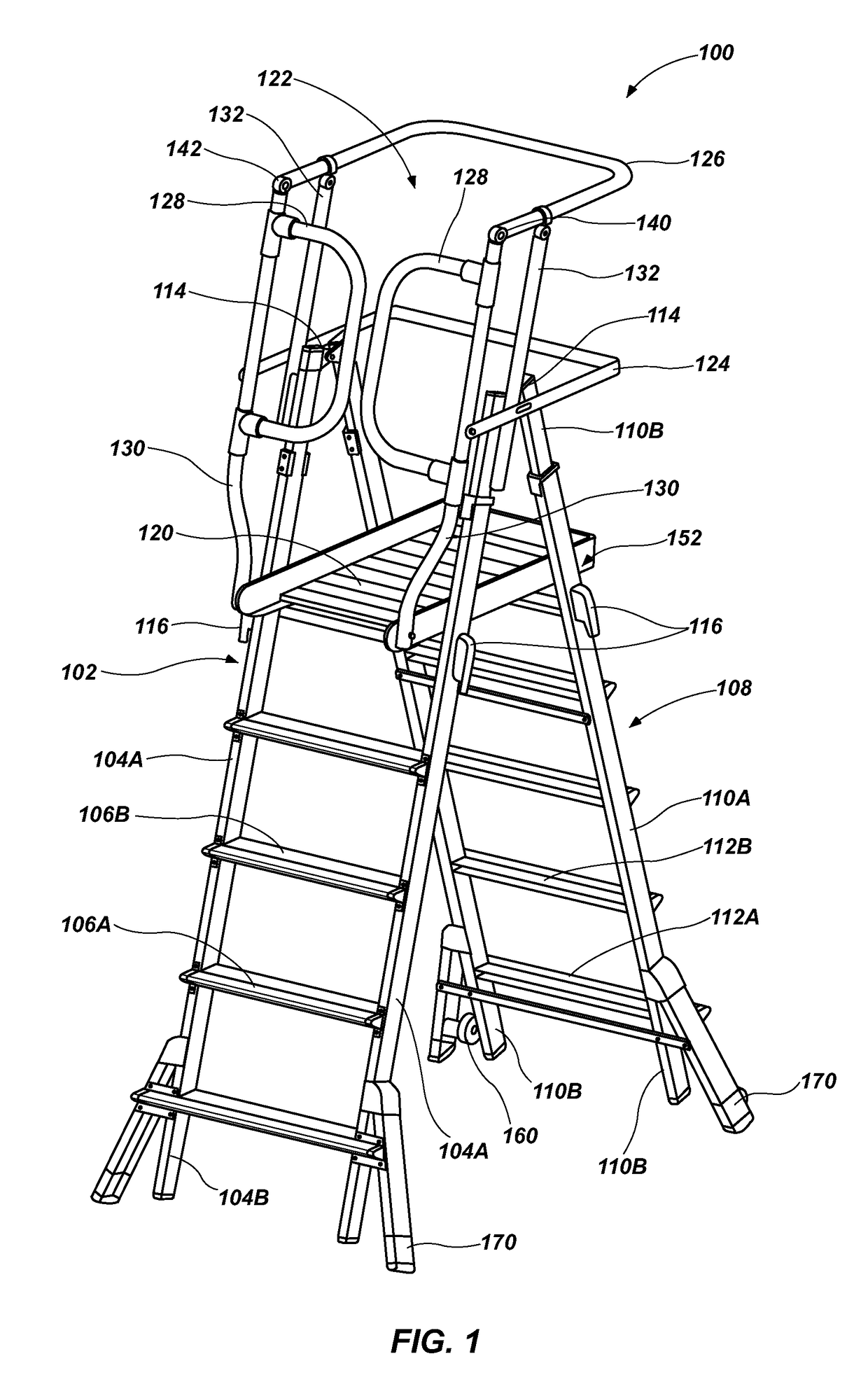
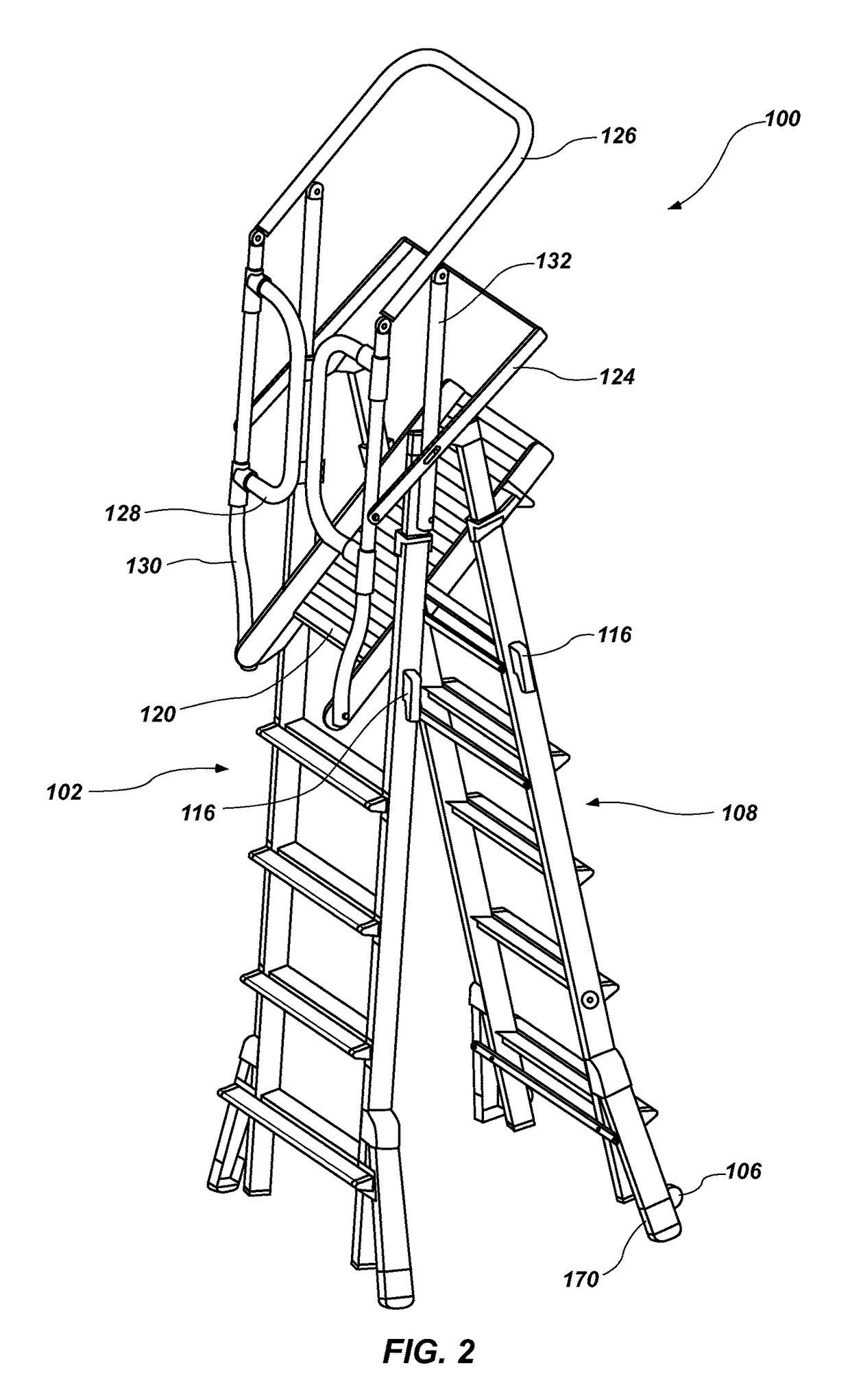
[0035]Referring to FIGS. 1-3, an elevated platform apparatus 100 is shown (referred to herein as the “apparatus” for purposes of convenience). The apparatus 100 includes a first assembly 102 having a first pair of spaced apart rails 104A with a plurality of rungs 106A extending between, and coupled to, the rails 104A. The rungs 106A are substantially evenly spaced, parallel to one another, and are configured to be substantially level when the apparatus 100 is in an orientation for intended use, so that they may be used as “steps” for a user to ascend (or descend) the apparatus 100. The first pair of rails 104A and their associated rungs 106A may be referred to as an outer rail assembly. The first assembly 102 may further include a second pair of spaced apart rails 104B with a plurality of rungs 106B extending between, and coupled to, the rails 104B. Again, the rungs 106B are evenly spaced, parallel to one another, and are configured to be substantially level when the apparatus 100 i...


PUM


Abstract

Elevated work platforms, as well as associated methods, are provided. In one particular embodiment, an elevated platform apparatus is provided comprising a first rail assembly having a pair of rails coupled with a plurality of rungs, a second rail assembly hingedly coupled with the first rail assembly, a platform configured to rest upon a portion of the first rail assembly and the second rails assembly and a cage associated with the platform. The cage may include at least one bar and at least one gate, the at least one gate being configured to swing in a first direction upon a user stepping on to the platform from the first rail assembly, and then swing back to a closed position after the user is standing on the platform. The at least one gate is also limited from being displaced in a second direction, opposite the first direction, beyond the closed position.

Description

CROSS-REFERENCE TO RELATED APPLICATION[0001]This application claims the benefit of U.S. Provisional Patent Application No. 61 / 589,790 entitled PLATFORM LADDER AND RELATED METHODS, filed on Jan. 23, 2012, the disclosure of which is incorporated by reference herein in its entirety.TECHNICAL FIELD[0002]The present invention relates generally to elevated working platforms related methods.BACKGROUND[0003]Ladders are one type of apparatus conventionally used to provide a user with improved access to elevated locations that might otherwise be difficult to reach. One of the advantages of ladders is their convenience. Ladders are easily transported from one location to another, generally easy to set up and use at a specific location, and easy to store when not in use. Ladders come in many sizes and configurations, such as straight ladders, extension ladders, stepladders, and combination step and extension ladders. So-called combination ladders may incorporate, in a single ladder, many of the...

Claims


Application Information

Patent Timeline
Patent Type & Authority Patents(United States)
IPC IPC(8): E06C1/00E06C5/32E06C1/393E06C1/397E06C7/42E06C7/18
CPCE06C1/393E06C1/397E06C7/182E06C7/185E06C7/423
Inventor MOSS, N. RYANPENROD, DARIUS S.RUSSELL, BRIANPETERSON, SEANJONAS, GARY
Owner LITTLE GIANT LADDER SYST LLC
Why Eureka
Try Eureka