Supercharge Your Innovation With Domain-Expert AI Agents!

Method and device for controlling energy distribution

A technology of energy distribution and control methods, applied in the field of energy management, can solve problems such as inability to operate the office and reduce the user experience of the office

Active Publication Date: 2020-07-14
ENN SCI & TECH DEV
View PDF5 Cites 0 Cited by
  • Summary
  • Abstract
  • Description
  • Claims
  • Application Information

AI Technical Summary

Problems solved by technology

[0004] The embodiment of the present invention provides an energy distribution control method and device, which solves the problem that in the prior art, energy supply equipment provides energy to offices with multiple rooms. When encountering peak hours, the total energy demanded by multiple offices is greater than the The total energy provided by the supply equipment per unit time prevents each office from operating according to the actual energy demand, thereby reducing the problem of user experience in the office

Method used


Image

  • Method and device for controlling energy distribution
  • Method and device for controlling energy distribution
  • Method and device for controlling energy distribution

Examples


Embodiment 1

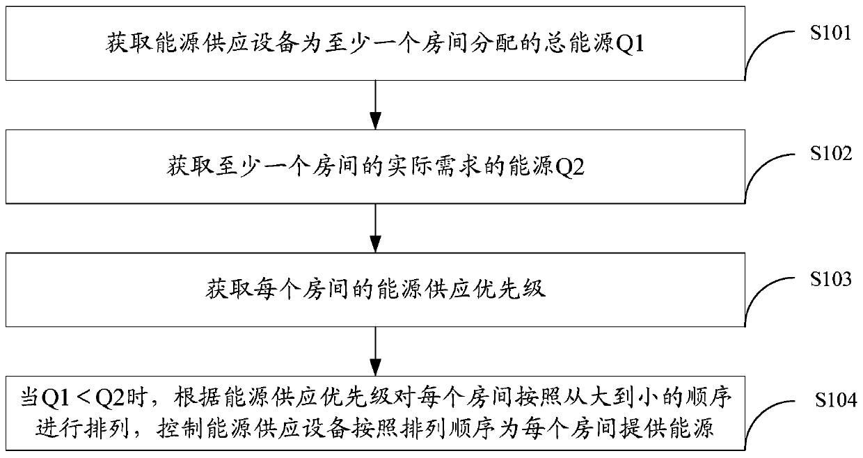
[0064] Embodiment 1. The embodiment of the present invention provides an energy distribution control method, such as figure 1 Shown include:

[0065] S101. Obtain the total energy Q1 distributed by the energy supply equipment to at least one room.

[0066] S102. Obtain energy Q2 actually required by at least one room.

[0067] S103. Obtain the energy supply priority of each room.

[0068] S104. When Q1

[0069] The energy distribution control method provided by the embodiment of the present invention acquires the total energy Q1 distributed by the energy supply equipment for at least one room, and acquires the energy Q2 actually required by at least one room; and then judges the energy supply equipment by judging the sizes of Q1 and Q2 The energy provided for different equipment; among the...

Embodiment 2

[0070] Embodiment 2. The embodiment of the present invention provides an energy distribution control method, such as figure 1 Shown include:

[0071] S101. Obtain the total energy Q1 distributed by the energy supply equipment to at least one room.

[0072] S102. Obtain energy Q2 actually required by at least one room.

[0073] S103. Obtain the energy supply priority of each room.

[0074] It should be noted that since each room itself does not have an energy supply priority, it is necessary to set the energy supply priority according to the actual situation. The specific settings are as follows:

[0075] Specifically, obtain the energy supply priority of each room, including:

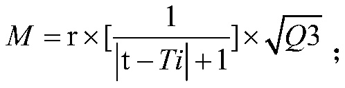
[0076] Obtain the coefficient value r preconfigured by the user for each room, where 0

[0077] Acquire the total energy demand Q3 of each room within the first preset time.

[0078] A peak schedule of energy demand of at least one room for a second preset time is obtained.

[0079] Construct...

Embodiment 3

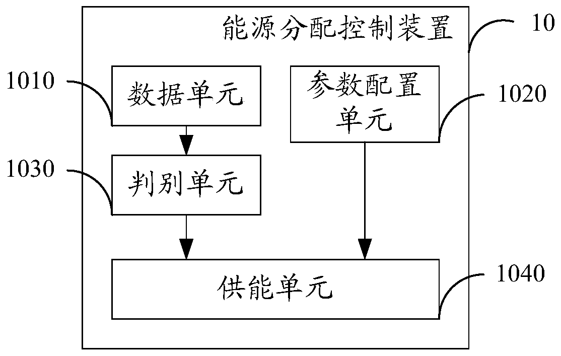
[0101]Embodiment 3, the embodiment of the present invention provides an energy distribution control device 10, such as figure 2 Shown include:

[0102] A data unit 1010, configured to obtain the total energy Q1 distributed by the energy supply equipment for at least one room;

[0103] The data unit 1010 is also used to acquire the energy Q2 actually required by at least one room;

[0104] A parameter configuration unit 1020, configured to acquire the energy supply priority of each room;

[0105] A judging unit 1030, configured to judge the size relationship between Q1 and Q2 acquired by the data unit 1010;

[0106] The energy supply unit 1040 is used for judging Q1

[0107] The energy distributi...


PUM


Abstract

Embodiments of the present invention provide an energy distribution control method and device, which relate to the technical field of energy management and solve the problem that energy supply equipment in the prior art provides energy to offices with multiple rooms. The total energy required is greater than the total energy provided by the energy supply equipment per unit time, so that each office cannot operate according to the energy actually required, thereby reducing the user experience of the office. The method includes obtaining the total energy Q1 distributed by the energy supply equipment for at least one room; obtaining the energy Q2 actually required by at least one room; obtaining the energy supply priority of each room; when Q1<Q2, according to the energy supply priority for each room The rooms are arranged in descending order, and the energy supply equipment is controlled to provide energy for each room in order. Embodiments of the present invention are used for energy distribution.

Description

technical field [0001] The invention relates to the technical field of energy management, in particular to an energy distribution control method and device. Background technique [0002] In the prior art, when energy supply equipment is used to provide energy to offices with multiple rooms, when multiple offices simultaneously issue instructions to obtain energy, the energy supply equipment needs to provide energy for different offices according to the received demand instructions from multiple offices. Offices provide different energy sources; since the total energy provided by the energy supply equipment in a unit time is certain, when encountering a peak period, the total energy demanded by multiple offices is greater than the total energy provided by the energy supply equipment in a unit time Energy; the energy supply equipment includes at least one or more of the following items: air-conditioning equipment, power generation equipment, and boiler equipment; therefore, th...

Claims


Application Information

Patent Timeline
Patent Type & Authority Patents(China)
IPC IPC(8): G06Q10/06
CPCG06Q10/0631
Inventor 李红霞曹雪源朱晓军武海滨甘中学
Owner ENN SCI & TECH DEV
Features
  • R&D
  • Intellectual Property
  • Life Sciences
  • Materials
  • Tech Scout
  • Unparalleled Data Quality
  • Higher Quality Content
  • 60% Fewer Hallucinations
Learn More