Eureka AIR delivers breakthrough ideas for toughest innovation challenges, trusted by R&D personnel around the world.

Water-absorbing floor wiper

A wiper and water-absorbing technology, which is applied in cleaning floors, carpets, cleaning equipment, etc., can solve problems such as unsatisfactory water absorption, wipers cannot absorb water, and people's soles slip, so as to improve the efficiency of wiping , Simplify the sewage removal process and improve the water absorption efficiency

Inactive Publication Date: 2017-06-06
龙能城市运营管理股份有限公司
View PDF5 Cites 10 Cited by
  • Summary
  • Abstract
  • Description
  • Claims
  • Application Information

AI Technical Summary

Problems solved by technology

[0002] The floor tiles are beautiful but do not absorb water. If the water stains left on the floor are not cleaned in time, they will leave footprints when people walk, which requires staff to clean them again. At the same time, because the surface of the floor tiles is relatively smooth, if there is water It is easy to make people's soles slip, so that some unnecessary safety accidents occur
In some shopping malls or office buildings with high turnover of people, after cleaning the ground, the staff will use absorbent mops or wipers to remove the accumulated water on the ground as soon as possible. The mop only contains a water-absorbing sponge head, which leads to its limited water-absorbing capacity. At the same time, the floor after cleaning with an absorbent mop is still wet, and the water-absorbing effect is not ideal; although the wiper can wipe water, it cannot absorb water. When there is a lot of accumulated water scraped, the scraping work of the wiper blade cannot be carried out smoothly

Method used


Image

  • Water-absorbing floor wiper
  • Water-absorbing floor wiper
  • Water-absorbing floor wiper

Examples


Embodiment Construction

[0021] Below will combine specific embodiment and appended Figure 1-5 , clearly and completely describe the technical solutions in the embodiments of the present invention, obviously, the described embodiments are only some preferred embodiments of the present invention, not all the embodiments. Those skilled in the art can make similar modifications without departing from the connotation of the present invention, so the present invention is not limited by the specific embodiments disclosed below.

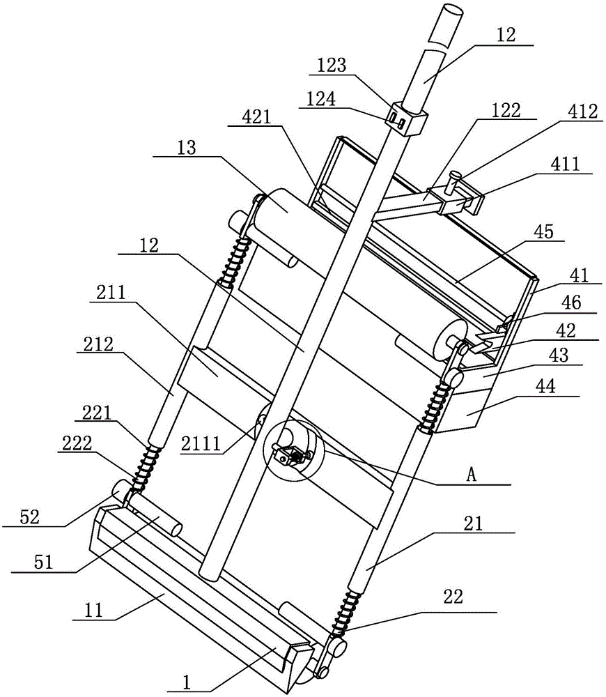
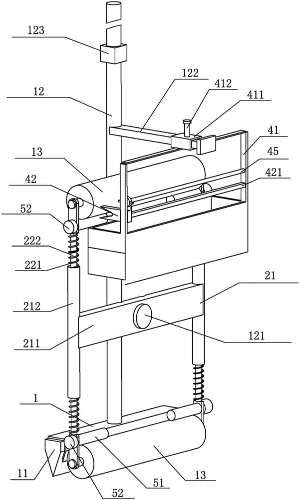
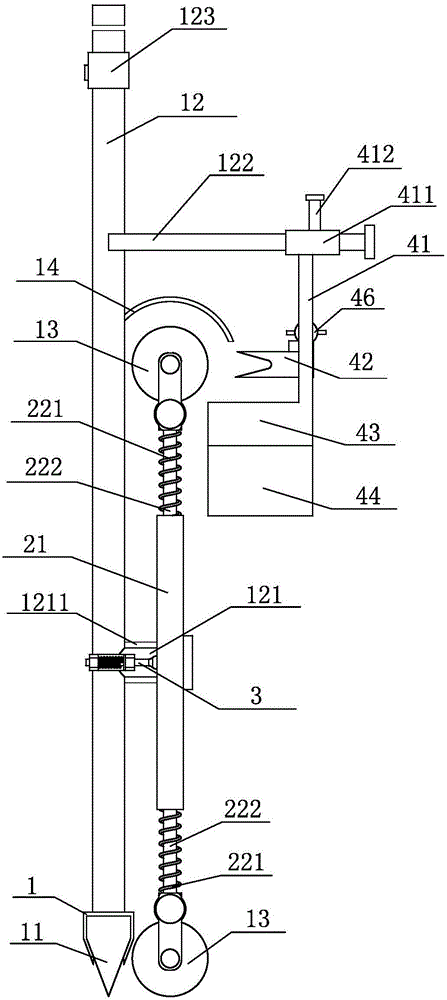
[0022] The invention provides a water-absorbing floor wiper (such as figure 1 shown), including a scraper body 1 and a push rod 12 arranged on the scraper body 1, a wiper rubber strip 11 is arranged in the scraper body 1, and the wiper rubber strip 11 is pressed on the scraper body 1 Inside, after a long time of use, the wiper rubber strip 11 can be removed from the wiper head body 1, and then a new wiper rubber strip 11 can be replaced. The wiper also includes a water absorbing...


PUM


Abstract

The invention provides a water-absorbing floor wiper. The wiper comprises a wiper head body, a water absorbing device and a water squeezing device. A water squeezing adhesive tape and a push rod are arranged on the shave head body. The water absorbing device comprises a 'H'-type holder and a sponge water absorbing roller. A position-limit mechanism is arranged on the push rod. The position-limit mechanism comprises a U-type holder, a second spring and a position-limit rod. The water squeezing device comprises a water squeezing holder, a U-type water squeezing board, a receiving groove of waste water and a storage box of waste water. A square casing at the upper end of the water squeezing holder covers a first square guide rod disposed on the upper part of the push rod. The U-type water squeezing board, the receiving groove of waste water and the storage box of waste water are arranged on the water squeezing holder from high to low. The sponge water absorbing roller can absorb the accumulated water on the floor squeezed through the water squeezing adhesive tape at the first sign of trouble, so that the problems that the back area of the water squeezing adhesive tape exists the accumulated water is avoided. At the same time, the two sponge water absorbing rollers can absorb the water and squeeze the water intermittently, so as to make the water squeezing adhesive tape do water squeezing work smoothly.

Description

technical field [0001] The invention relates to a water-absorbing floor wiper. Background technique [0002] The floor tiles are beautiful but do not absorb water. If the water stains left on the floor are not cleaned in time, they will leave footprints when people walk, which requires staff to clean them again. At the same time, because the surface of the floor tiles is relatively smooth, if there is water It is easy to make people's soles slip, so that some unnecessary safety accidents take place. In some shopping malls or office buildings with high turnover of people, after cleaning the ground, the staff will use absorbent mops or wipers to remove the accumulated water on the ground as soon as possible. The mop only contains a water-absorbing sponge head, which leads to its limited water-absorbing capacity. At the same time, the floor after cleaning with an absorbent mop is still wet, and the water-absorbing effect is not ideal; although the wiper can wipe water, it cann...

Claims


Application Information

Patent Timeline
Patent Type & Authority Applications(China)
IPC IPC(8): A47L13/12A47L13/42
CPCA47L13/12A47L13/42
Inventor 李金雨
Owner 龙能城市运营管理股份有限公司
Why Eureka
Eureka Blog
Learn More