
Turning bed

A turning bed and bed board technology, which is applied in the field of turning beds, can solve the problems of large space occupied by the whole bed board, sideways sliding, cumbersome maintenance, etc., and achieve the effects of convenient transportation and maintenance, increasing comfort and reducing the feeling of slipping

Inactive Publication Date: 2017-06-06
广东勤联长实科技有限公司
View PDF16 Cites 6 Cited by
  • Summary
  • Abstract
  • Description
  • Claims
  • Application Information

AI Technical Summary

Problems solved by technology

[0002] At present, most of the functional medical beds used in major hospitals do not have the function of turning over left and right. The way that an existing medical bed realizes turning over left and right is: the whole bed board is wound around its length direction through a linkage mechanism. The central axis of the bed rotates. This way of turning over is likely to cause the patient's center of gravity to be unstable, and it is easy to cause sideways sliding, which makes the patient feel uncomfortable. Moreover, the overall bed board takes up a lot of space, which is inconvenient for transportation, disassembly and maintenance.
As a result, modular replacement cannot be performed during maintenance, resulting in cumbersome maintenance

Method used


Image

  • Turning bed
  • Turning bed
  • Turning bed

Examples


Embodiment 1

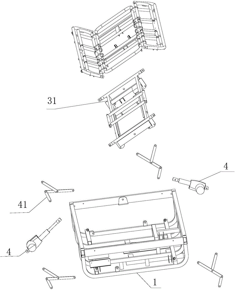
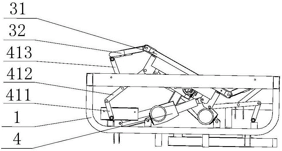
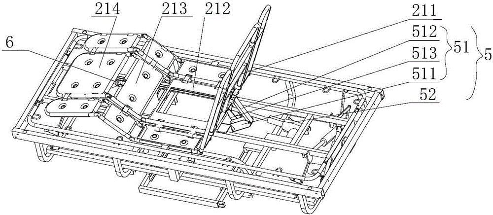
[0040] refer to Figure 1 to Figure 6 , the present embodiment provides a turning bed, which includes an upper bed frame assembly 1, a bed board assembly 2 and a middle frame assembly 3, the middle frame assembly 3 is installed on the upper bed frame assembly 1, and each of the two ends is connected to the upper bed frame assembly 1 through a connecting shaft. The two ends of the frame are rotatably connected, and the middle frame assembly 3 includes a middle frame 31 and side frames 32 located on the left and right sides, which are respectively rotatably connected with the middle frame 31 . The middle parts of the two ends of the middle bracket 31 are rotatably connected with the middle parts of the two ends of the upper bed frame assembly 1 through a connecting shaft. Specifically, the middle parts of the head end and the tail end of the upper bed frame assembly 1 are respectively provided with an ear seat, and each ear seat is fixed Connect a connecting shaft, the middle pa...


PUM


Abstract

The invention relates to field of medical instruments, in particular to a turning bed which comprises an upper bed frame component, a bed plate component, a middle frame component, a first drive device and connecting rod mechanisms. The middle frame component is mounted on the upper bed frame component, two ends of the middle frame component are rotatably connected with two ends of the upper bed frame component through connecting shafts, the middle frame component comprises a middle support, a left support and a right support, the left support and the right support are positioned on the left side and the right side of the middle support and respectively and rotatably connected with the middle support, the bed plate component comprises a middle bed plate, a left bed plate and a right bed plate, the left bed plate and the right bed plate are positioned on the left side and the right side of the middle bed plate and respectively and rotatably connected with the middle bed plate, the middle bed plate is fixedly mounted on the middle support of the middle frame component, the left bed plate and the right bed plate are correspondingly placed on the left support and the right support, the connecting rod mechanisms are arranged on the left side and the right side of the turning bed, one end of the first driving device is connected with the upper bed frame component, the other end of the first driving device is hinged to the middle support, and the left connecting rod mechanism and the right connecting rod mechanism are hinged to the middle support, the left support, the right support and the upper bed component respectively. The turning bed has the advantages that a patient comfortably turns over, and the turning bed is convenient to transport, disassemble, assemble and maintain.

Description

technical field [0001] The invention relates to the field of medical equipment, in particular to a turning bed. Background technique [0002] At present, most of the functional medical beds used in major hospitals do not have the function of turning over left and right. The way that an existing medical bed realizes turning over left and right is: the whole bed board is wound around its length direction through a linkage mechanism. The central axis of the bed rotates, and this way of turning over can easily cause the patient's center of gravity to be unstable, and it is easy to cause sideways sliding, which makes the patient feel uncomfortable, and the overall bed board takes up a lot of space, which is inconvenient for transportation, disassembly and maintenance. As a result, modular replacement cannot be performed during maintenance, resulting in cumbersome maintenance. [0003] Therefore, urgently need a kind of turning bed that can make patient stand up more comfortable,...

Claims


Application Information

Patent Timeline
Patent Type & Authority Applications(China)
IPC IPC(8): A61G7/00A61G7/015A61G7/057
CPCA61G7/001A61G7/015A61G7/018A61G7/057
Inventor 黄劲涛
Owner 广东勤联长实科技有限公司
Learn More