An intelligent pinch roller and its control method
A pinch roller, intelligent technology, applied in the field of intelligent pinch roller and its control, can solve the problems of plastic deformation, wire slipping, and the inability to dynamically adjust the clamping force of the pinch roller, etc., to achieve the effect of avoiding plastic deformation
- Summary
- Abstract
- Description
- Claims
- Application Information
AI Technical Summary
Problems solved by technology
Method used
Image
Examples
Embodiment 1
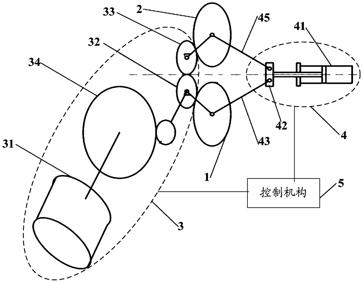
[0060] Such as image 3 As shown, the embodiment of the present invention provides an intelligent pinch roller, which specifically includes: a first pinch roller body 1 , a second pinch roller body 2 , a transmission mechanism 3 , a servo mechanism 4 and a control mechanism 5 .
[0061] Wherein, the first pinch roller body 1 and the second pinch roller body 2 are arranged oppositely, the wire to be processed is placed between the first pinch roller body 1 and the second pinch roller body 2, and the first pinch roller body 1 and the clamping force extrusion between the second pinch roller body 2.
[0062] The first pinch roller body 1 and the second pinch roller body 2 are connected to the transmission mechanism 3 respectively, and under the action of the transmission mechanism 3, the first pinch roller body 1 and the second pinch roller body 2 rotate around their own axial directions respectively. Rotate to achieve the purpose of conveying wire.
[0063] The first pinch roll...
Embodiment 2
[0066] The first embodiment above briefly introduces the functional components of the intelligent pinch roller of the present invention, and will be further described below in conjunction with the specific implementation structure of each functional component.
[0067] Specifically, such as image 3 and Figure 4 As shown, the transmission mechanism 3 includes: a driving motor 31 , a first transmission gear 32 , and a second transmission gear 33 . Wherein, the first transmission gear 32 is connected with the driving motor 31, the second transmission gear 33 is meshed with the first transmission gear 32, and the driving motor 31 is used to provide driving force for the first transmission gear 32, under the action of the driving motor 31 , the first transmission gear 32 can rotate around its own axial direction, and can further drive the second transmission gear 33 to rotate around its own axial direction through gear cooperation, wherein the first transmission gear 32 and the ...
Embodiment 3
[0074] The first and second embodiments above introduced the specific implementation structure of the intelligent pinch roller of the present invention, and the following embodiment three will further introduce the control method of the intelligent pinch roller.
[0075] Wherein, the control method specifically includes the following steps:
[0076] The control mechanism collects the clamping force between the first pinch roller body and the second pinch roller body, or collects the output torque of the transmission mechanism. During the normal working process of the intelligent pinch roller, the clamping force between the first pinch roller body and the second pinch roller body, or the output torque of the transmission mechanism is collected and detected in real time, so as to know the processing status of the wire in real time.
[0077] According to the preset input-output relationship, calculate the clamping force or output torque, and obtain the control signal for controll...
PUM
 Abstract
Description
Claims
Application Information
 - R&D
- Intellectual Property
- Life Sciences
- Materials
- Tech Scout
- Unparalleled Data Quality
- Higher Quality Content
- 60% Fewer Hallucinations
Browse by: Latest US Patents, China's latest patents, Technical Efficacy Thesaurus, Application Domain, Technology Topic, Popular Technical Reports.
© 2025 PatSnap. All rights reserved.Legal|Privacy policy|Modern Slavery Act Transparency Statement|Sitemap|About US| Contact US: help@patsnap.com


