Active control hydraulic suspending structure

A hydraulic suspension and active control technology, applied in the direction of shock absorbers, springs, spring/shock absorbers, etc., can solve the problem of passive adjustment of suspension cushions with the outside world

Active Publication Date: 2017-06-13
ANHUI JIANGHUAI AUTOMOBILE GRP CORP LTD
View PDF6 Cites 0 Cited by
  • Summary
  • Abstract
  • Description
  • Claims
  • Application Information

AI Technical Summary

Problems solved by technology

[0005] The purpose of the present invention is to provide an active control hydraulic suspension structure to solve the problem that the suspension cushion in the prior art can only be adjusted passively with the outside world

Method used


Image

  • Active control hydraulic suspending structure
  • Active control hydraulic suspending structure
  • Active control hydraulic suspending structure

Examples


Embodiment 1

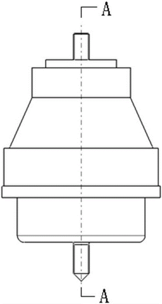
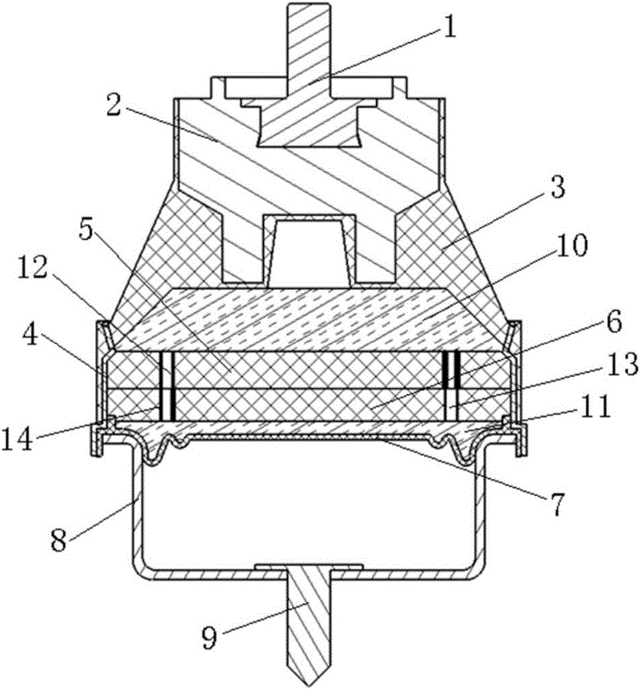
[0032] This application provides an active control hydraulic mount structure, such as Figure 1 to Figure 6 As shown, it includes upper mounting bolt 1, metal frame 2, rubber main spring 3, suspension shell 4, suspension bottom shell 8, lower mounting bolt 9, rubber base film 7, upper partition 5 and lower partition 6, In each embodiment of the present application, the above-mentioned components of the hydraulic mount structure are all prior art, and the applicant will not describe them in detail here.

[0033] The upper mounting bolts are fixed on the metal frame, and the metal frame, the rubber main spring and the suspension shell are vulcanized into one structure, which is also a prior art.

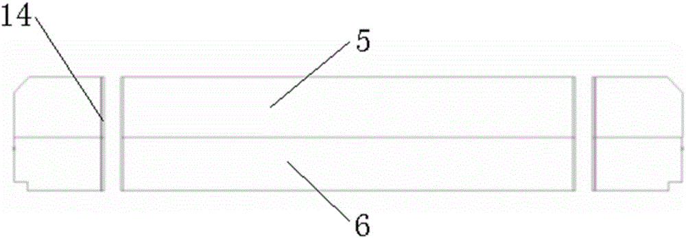
[0034] An upper partition and a lower partition are arranged in the suspension housing, and a rubber bottom film is provided at the lower end of the suspension housing; in this application, the lower surface of the upper partition is attached to the upper surface of the lower partition...

Embodiment 2

[0046] In this embodiment, other structures of the hydraulic mount are the same, and the only difference is the structure of the ring electrode.

[0047] In this embodiment, the ring electrode includes a first ring electrode and a second ring electrode, the first ring electrode is arranged in the upper inertial channel, and the second ring electrode is arranged in the lower inertial channel.

[0048] In this way, after the pressure signal transmitted by the sensor is transmitted to the control board, the magnitude and direction of the current of the corresponding ring electrode can be controlled respectively, so that the control of the hydraulic mount is more flexible.


PUM


Abstract

The invention relates to an active control hydraulic suspending structure, comprising an upper installing bolt, a metal framework, a main rubber spring, a suspending shell, a suspending bottom shell, a lower installing bolt, a rubber base film, an upper clapboard, a lower clapboard, a sensor, an annular electrode and a control plate. Through adding the annular electrode on the basis of the traditional suspension, outside pressure is transmitted to the control plate through an electric signal after the sensor judges the outside pressure, and the control plate controls power output according to the pressure change and changes the electro-hydraulic or voltage intensity output to the annular electrode or changes the current direction, thus corresponding annular electrode material is contracted or expanded, so as to change the size of the inside diameter of a corresponding inertia channel, and reach the purpose of changing the suspending rigidity.

Description

technical field [0001] The invention belongs to the technical field of engine mounts, in particular to an active control hydraulic mount structure. Background technique [0002] The automobile engine is arranged on the chassis, and the frame and the engine are connected through the engine suspension cushion; the engine cushion must have the function of attenuating engine vibration while supporting the engine, and ensuring that the engine displacement does not exceed the design allowable range under various working conditions. [0003] The traditional suspension cushion is composed of rubber main spring, inertia channel, decoupling diaphragm, throttle plate, connecting bolts and rubber bottom film, etc. When the suspension is excited by low frequency and large scale, the displacement amplitude of the decoupling diaphragm Larger, reaching its upper limit and lower limit position, the liquid mainly flows between the upper liquid chamber and the lower liquid chamber through the ...

Claims


Application Information

Patent Timeline
Patent Type & Authority Applications(China)
IPC IPC(8): F16F13/08F16F13/26
CPCF16F13/08F16F13/26
Inventor 迟玉华杨大芝龚将伟蔡欣
Owner ANHUI JIANGHUAI AUTOMOBILE GRP CORP LTD
Why Eureka
Try Eureka