Dredging type oil mist sealing method

A technology of oil mist and sealing cover, which is applied in the direction of engine sealing, engine components, engine lubrication, etc., can solve the problems of ineffective sealing, failure to achieve suction effect, difficulty in mastering, etc., and achieve the effect of avoiding oil shortage of bearings

Active Publication Date: 2017-06-13
四川白合轴承技术有限公司
View PDF7 Cites 6 Cited by
  • Summary
  • Abstract
  • Description
  • Claims
  • Application Information

AI Technical Summary

Problems solved by technology

Due to the large change in air pressure, it is difficult to control, and there is a forced power, which leads to either the excessive suction capacity, forcing the oil mist to overflow, or the weak suction capacity, which cannot achieve the suction effect and the seal is invalid.

Method used


Image

  • Dredging type oil mist sealing method
  • Dredging type oil mist sealing method
  • Dredging type oil mist sealing method

Examples


Embodiment 1

[0027] This embodiment is mainly applied to a dredging-type oil mist sealing method used by a unidirectional rotating unit.

[0028] A dredging type oil mist sealing method, is characterized in that, comprises the following steps:

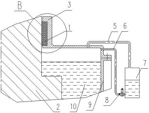
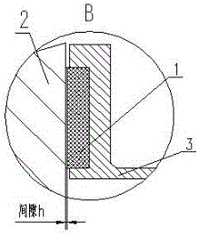
[0029] (1) An oil mist sealing device is installed on the oil tank; the oil mist sealing device includes a sealing cover, an oil collection tank 7, an oil suction pipe 6 and a sealing cover oil overflow pipe 5, and the rotation direction and the rotation of the rotating shaft 2 are provided on the sealing surface of the sealing cover The thread tooth structure 1 in the opposite direction, there is a gap between the thread tooth structure and the rotating shaft;

[0030] (2) When the unit is rotating, the oil pressure existing on the sealing surface is injected into the oil groove by utilizing the fluid viscosity, the rotation direction of the unit and the rotation direction of the thread teeth, and the pressure of the oil mist in the oil groove ris...

Embodiment 2

[0046] This embodiment is mainly applied to a dredge-type oil mist sealing method used in bidirectional rotating units.

[0047] A dredging type oil mist sealing method, comprising the following steps:

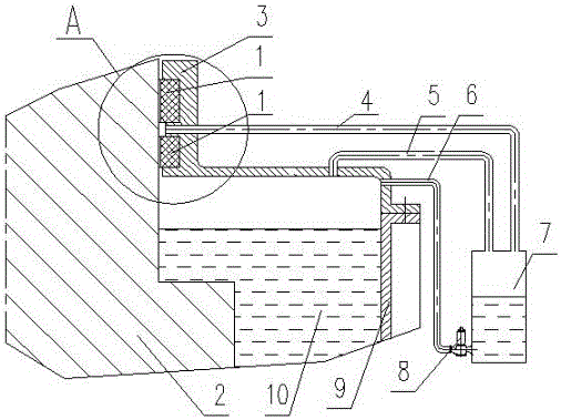
[0048] (a1) Install an oil mist sealing device on the oil tank. The oil mist sealing device includes a sealing cover, an oil collection tank, a sealed interdental oil overflow pipe, an oil suction pipe and a sealing cover oil overflow pipe. There is a tooth rotation direction on the sealing surface of the sealing cover. The opposite two thread tooth structures, there is a gap between the two thread tooth structures and the rotating shaft; the heights of the two thread tooth structures are different, when the unit rotates, the thread tooth structure located at the bottom of the above two thread tooth structures and the rotation direction of the unit On the contrary, perform the following step (a2); when the unit rotates, and the lower thread tooth structure of the above two thr...


PUM


Abstract

The invention discloses a dredging type oil mist sealing method. The method solves the problems that in the prior art, oil mist greatly overflows in clearance type sealing, abrasion and heating are likely to happen in contact sealing, forcefully discharged oil mist is hardly balanced with oil groove air pressure, and sealing fails. The dredging type oil mist sealing method includes the following steps that firstly, an oil groove is provided with an oil mist sealing device, the oil mist sealing device comprises a sealing cover, an oil collection tank, an oil suction pipe and a sealing cover oil overflow pipe, the sealing face of the sealing cover is provided with threaded tooth structures with the rotating direction opposite to the rotating direction of a rotating shaft, and a clearances exist between the threaded tooth structures and the rotating shaft; secondly, when a unit rotates, oil gas existing on the sealing face is pressed into an oil groove oil overflow pipe or a sealing inter-tooth oil overflow pipe through cooperation of fluid viscosity, the unit rotating direction and the threaded tooth rotating direction and is led into the oil collection tank; and thirdly, after the unit is stopped, lubricating oil in the oil collection tank is sucked back into the oil groove by an oil suction pump through the oil suction pipe, and oil shortage of a bearing when the unit is started is avoided.

Description

technical field [0001] The invention is applicable to the technical field of sliding bearings, and in particular relates to a dredging type oil mist sealing method. Background technique [0002] On vertical rotating electrical machines, the bearing oil sump holds lubricating oil for lubricating the guide or thrust bearings. The motor rotates, the bearings work and agitate the oil flow in the oil sump, thereby forming an oil mist in the oil sump. [0003] Usually, the bearing oil tank is provided with a sealing cover to prevent the oil mist from overflowing in the oil tank and avoid polluting the motor and the environment. The existing seal adopts gap seal or follow-up contact seal. [0004] A typical structure of the gap seal is a labyrinth seal. Several circles of grooves are made on the sealing surface (or soft wear-resistant materials are filled in the grooves) to increase the resistance of the oil mist passing through the seal gap to achieve the seal. Effect, see "Hyd...

Claims


Application Information

Patent Timeline
Patent Type & Authority Applications(China)
IPC IPC(8): F16N7/32F16J15/16
CPCF16J15/162F16N7/32
Inventor 万宇
Owner 四川白合轴承技术有限公司
Why Eureka
Try Eureka