Check patentability & draft patents in minutes with Patsnap Eureka AI!

PDAF function detection machine for camera modules and detection method of PDAF function detection machine

A camera module and functional testing machine technology, applied in photography, optics, instruments, etc., can solve the problems of low testing efficiency, inability to meet industrial needs, complex testing structure of testing machines, etc., to achieve high testing efficiency, high degree of automation, Check for full effect

Active Publication Date: 2017-06-13
深圳眼千里科技有限公司
View PDF7 Cites 5 Cited by
  • Summary
  • Abstract
  • Description
  • Claims
  • Application Information

AI Technical Summary

Problems solved by technology

However, the existing detectors have complex detection structures and low detection efficiency, which cannot meet industrial needs

Method used


Image

  • PDAF function detection machine for camera modules and detection method of PDAF function detection machine
  • PDAF function detection machine for camera modules and detection method of PDAF function detection machine
  • PDAF function detection machine for camera modules and detection method of PDAF function detection machine

Examples


Embodiment Construction

[0030] Below, in conjunction with accompanying drawing and specific embodiment, the present invention is described further:

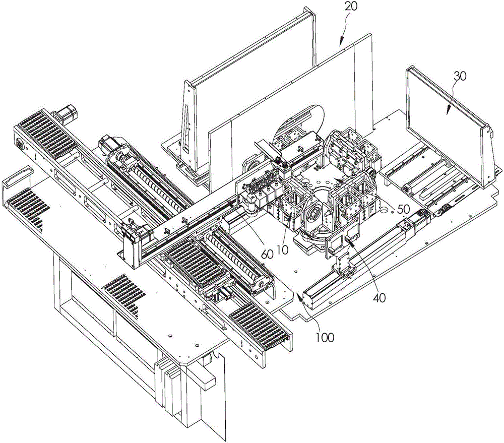
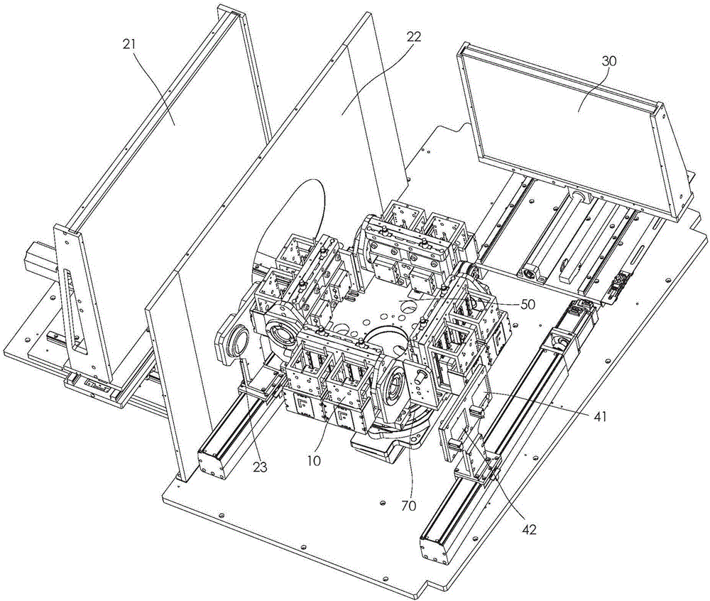
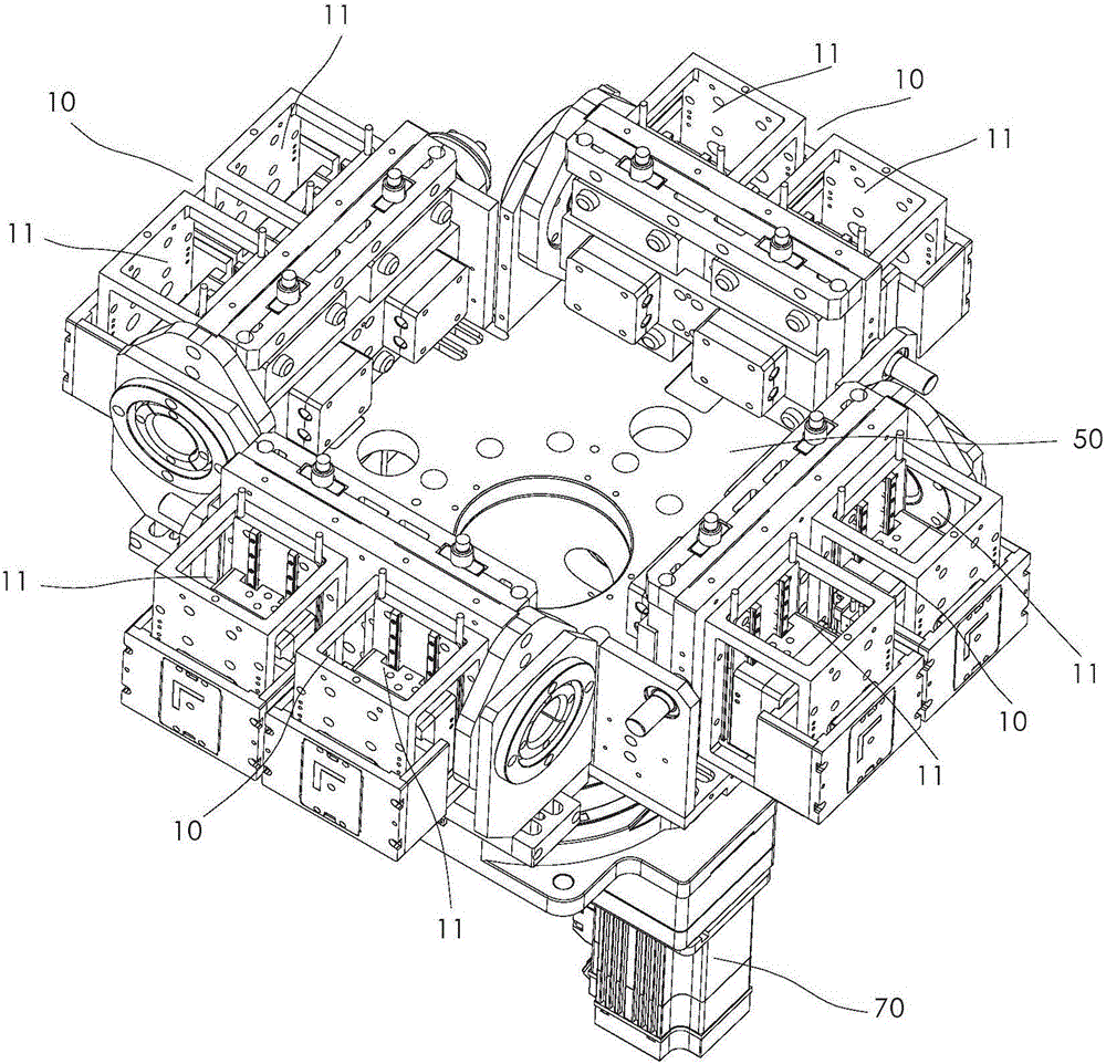
[0031] Such as Figure 1-4 The shown camera module PDAF function testing machine includes a body 100 and a conveying mechanism installed on the body 100 . The body 100 is provided with a plurality of detection stations 10, a long-range detection mechanism 20, a close-up detection mechanism 30, and a black-and-white field detection mechanism 40. The above-mentioned multiple detection stations 10 can be transported along a first conveying mechanism under the drive of the above-mentioned conveying mechanism. The directions are cyclically and staggered and sent to the distant view detection mechanism 20 , the close view detection mechanism 30 , and the black and white field detection mechanism 40 in sequence.

[0032] On the basis of the above structure, when using the camera module PDAF function detection machine of the present invention, a feeding statio...


PUM


Abstract

The invention discloses a PDAF function detection machine for camera modules. The PDAF function detection machine comprises a machine body and a conveying mechanism, wherein the machine body is provided with a plurality of detection stations, a long shot detection mechanism, a close shot detection mechanism and a black and white field detection mechanism; the plurality of detection stations sequentially convey the long shot detection mechanism, the close shot detection mechanism and the black and white field detection mechanism in a staggered cycle along a first conveying direction; the conveying mechanism is used for conveying the plurality of detection stations to the long shot detection mechanism, the close shot detection mechanism and the black and white field detection mechanism to carry out PDAF function detection on the camera module. A detection method of the PDAF function detection machine for the camera modules comprises the following four steps. Testing of different focal distances, a white field and a black field of a plurality of camera modules is completed in one-time conveying process, and the detection efficiency is high.

Description

technical field [0001] The invention relates to the technical field of camera module testing equipment, in particular to a camera module PDAF function testing machine and a testing method thereof. Background technique [0002] PDAF is phase focusing. Its principle is to reserve some shaded pixels on the photosensitive element for phase detection. The distance between pixels and its changes are used to determine the offset value of the focus to achieve accurate focus. When performing detection, phase focusing does not need to adjust the front and rear of the mirror group to find the focus, but judges whether the current focus point is at the front or the back through the signal detected by the camera at the beginning of the focusing action, and accurately The new focusing driver module tells the lens to directly push the lens group to the accurate focus position. However, the existing detectors have complex detection structures and low detection efficiency, which cannot meet...

Claims


Application Information

Patent Timeline
IPC IPC(8): G03B43/00
CPCG03B43/00
Inventor 钟汉龙李书毅徐翼李久林雷茜
Owner 深圳眼千里科技有限公司
Features
  • R&D
  • Intellectual Property
  • Life Sciences
  • Materials
  • Tech Scout
  • Unparalleled Data Quality
  • Higher Quality Content
  • 60% Fewer Hallucinations
Learn More