

Key switch and keyboard using the key switch
A button and switch technology, applied in the direction of electric switches, electrical components, circuits, etc., can solve the problems of hindering the movement of the tongue and the inability to obtain the operating tactile feeling, and achieve the effect of good operating tactile feeling
- Summary
- Abstract
- Description
- Claims
- Application Information
AI Technical Summary
Problems solved by technology
Method used
Image

Examples
no. 1 approach
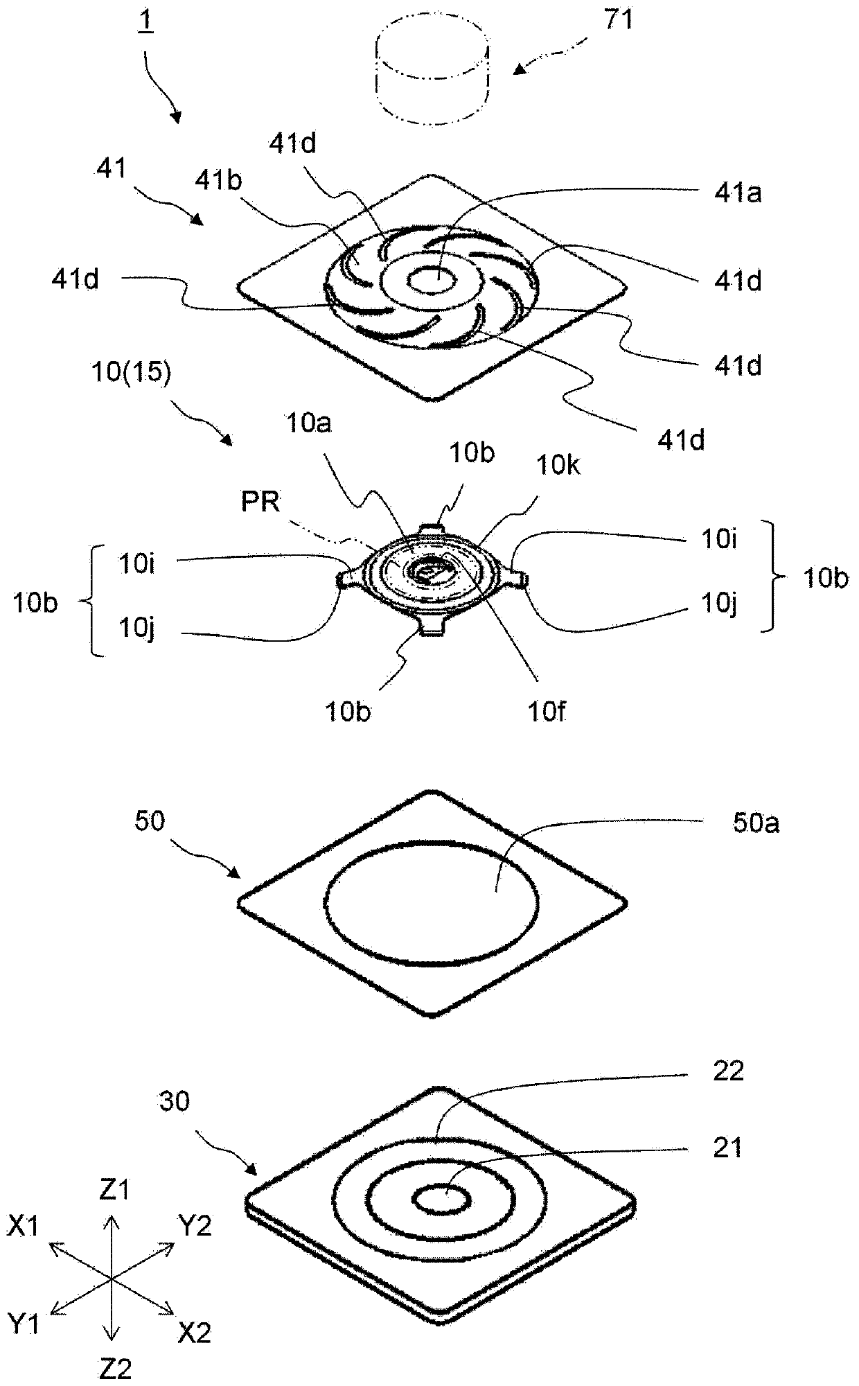
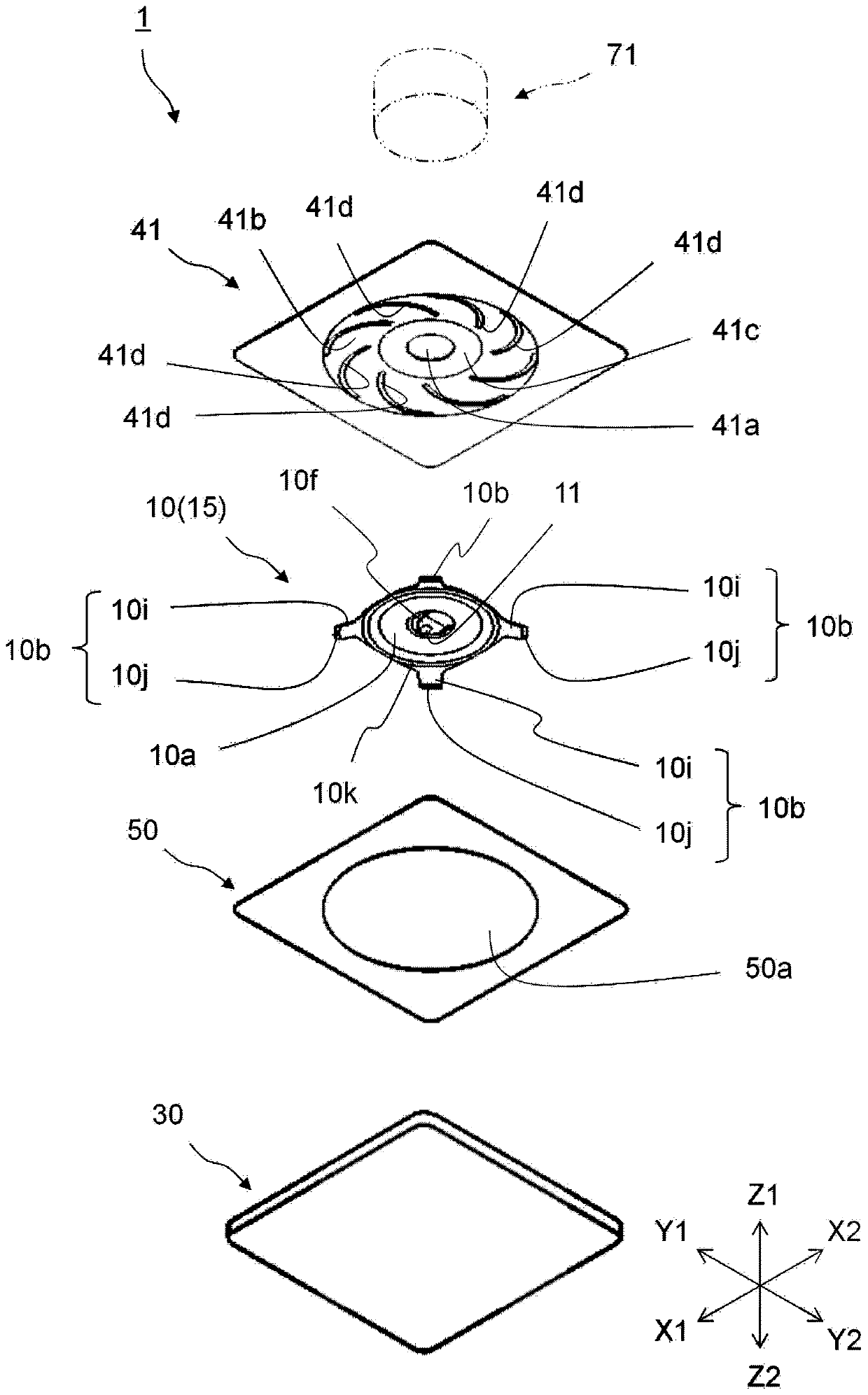
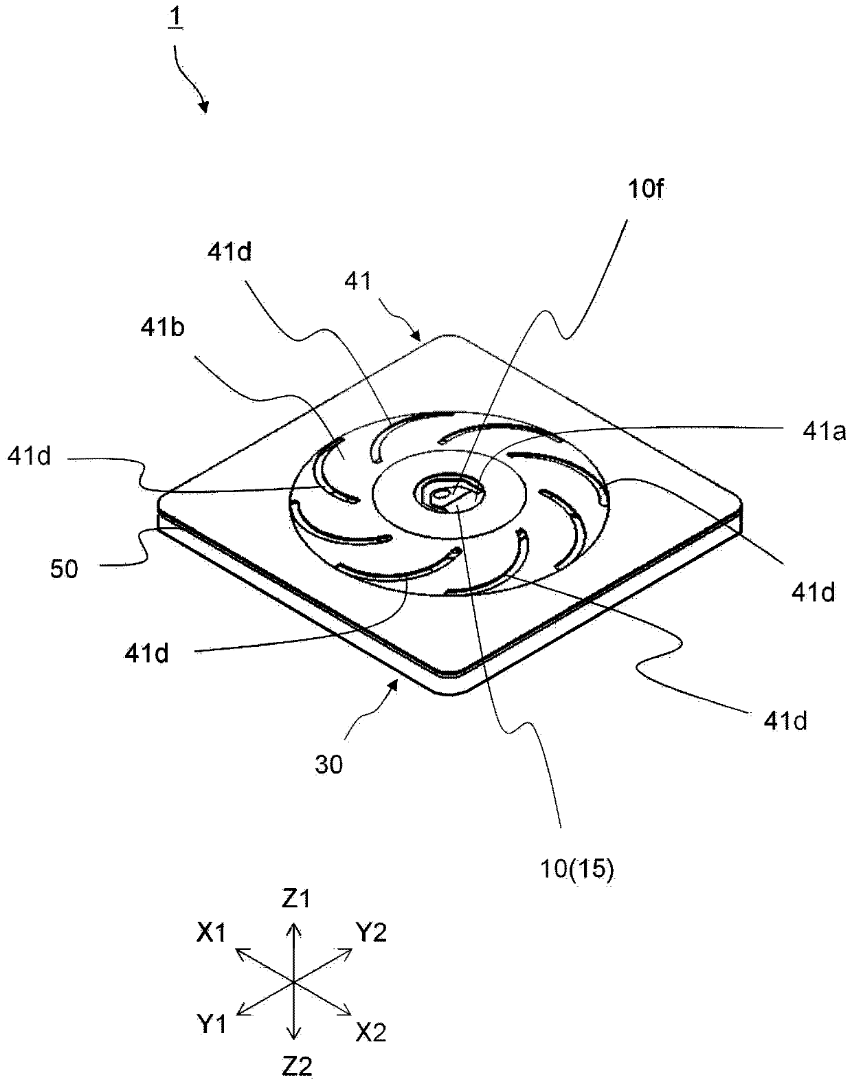
[0150] figure 1 It is an exploded perspective view of the key switch 1 according to the first embodiment of the present invention viewed obliquely from above. figure 2 It is an exploded perspective view of the key switch 1 viewed obliquely from below. image 3 It is a perspective view showing the key switch 1 . Figure 4 It is a plan view showing the key switch 1 . Figure 5 It is a front view showing the key switch 1 . Image 6 is a plan view showing the leaf spring member 10 . Figure 7 It is a bottom view showing the leaf spring member 10 . Figure 8 is a front view showing the leaf spring member 10 .
[0151] The key switch 1 according to the first embodiment includes: a leaf spring member 10 serving also as a movable contact member 15, a base member 30 on which a fixed contact member 21 and a supporting contact member 22 are disposed, a spacer member 50, and a sheet member. 41. It should be noted that, in Figure 1 to Figure 5 In the illustration, the key switch...
no. 2 approach
[0186] Figure 11 It is an exploded perspective view of the key switch 2 according to the second embodiment of the present invention viewed obliquely from above. Figure 12 It is an exploded perspective view of the key switch 2 viewed obliquely from below. Figure 13 It is a perspective view showing the key switch 2 . Figure 14 It is a plan view showing the key switch 2 .
[0187] The key switch 2 according to the second embodiment includes: a leaf spring member 10 serving also as a movable contact member 15 , a base member 30 on which a fixed contact member 21 is disposed, a sheet member 42 , and a sheet member integrated with the sheet member 42 . Press member 46 . It should be noted that among the members constituting the key switch 2 of the second embodiment, the same members as those of the key switch 1 of the first embodiment are shown with the same reference numerals regardless of the difference in shape, and are described below. The description of this component i...
no. 3 approach
[0208] Figure 17 It is an exploded perspective view of the push switch 3 according to the third embodiment of the present invention seen obliquely from above. Figure 18 It is an exploded perspective view of the key switch 3 viewed obliquely from below. Figure 19 It is a perspective view showing the key switch 3 . Figure 20 It is a plan view showing the key switch 3 . Figure 21 It is a front view showing the key switch 3 . Figure 22 is a plan view showing the leaf spring member 10 . Figure 23 It is a bottom view showing the leaf spring member 10 . Figure 24 is a front view showing the leaf spring member.
[0209] The key switch 3 of the third embodiment includes a leaf spring member 10 having a dome portion 10 a , a spacer member 50 , a sheet member 43 , and a switch member 60 . The switch member 60 is a diaphragm and includes: a fixed contact member 62 , a movable contact member 61 configured to be capable of contacting and separating from the fixed contact membe...
PUM
 Abstract
Description
Claims
Application Information