Switch control panel

A switch control and panel technology, applied in the direction of electric switches, tactile feedback, electrical components, etc., can solve the problems such as the inability to guarantee the consistency of the button 106 feel and the inconsistency in height, and achieve the effect of maintaining a consistent feel and eliminating feel errors.

Inactive Publication Date: 2017-06-13
FUZHOU ONER IND DESIGN CO LTD
View PDF6 Cites 2 Cited by
  • Summary
  • Abstract
  • Description
  • Claims
  • Application Information

AI Technical Summary

Problems solved by technology

In actual use, since the heights of the plurality of micro switches 105 on the circuit board 104 after welding cannot be consistent, it is impossible to guarantee the consistency of the hand feeling when the button 106 is pressed, or to ensure that the hand feel is optimal.

Method used


Image

  • Switch control panel
  • Switch control panel
  • Switch control panel

Examples


Embodiment 2

[0044] Please refer to Figure 3 to Figure 6 , the second embodiment of the present invention is:

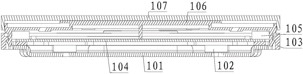
[0045] A switch control panel, on the basis of the first embodiment, the end side of the support body 3 facing the micro switch 2 is provided with a first groove 31 inwardly, and the first groove 31 is in the shape of a strip , an elastic member 32 is formed between adjacent first grooves 31, and the upper surface of the end of the elastic member 32 is higher than the height when the micro switch 2 is pressed, and is lower than the height of the micro switch 2 The height when lifted, the lower surface of the support body 3 has at least two first convex lines 33 extending downward, the support body 3 is in contact with the upper surface of the circuit board 1 through the first convex lines 33, so The end of the elastic member 32 is upwardly provided with a first protrusion 34, the upper surface of the first protrusion 34 is higher than the height of the micro switch 2 when it is...

Embodiment 3

[0046] Please refer to Figure 3 to Figure 6 , Embodiment three of the present invention is:

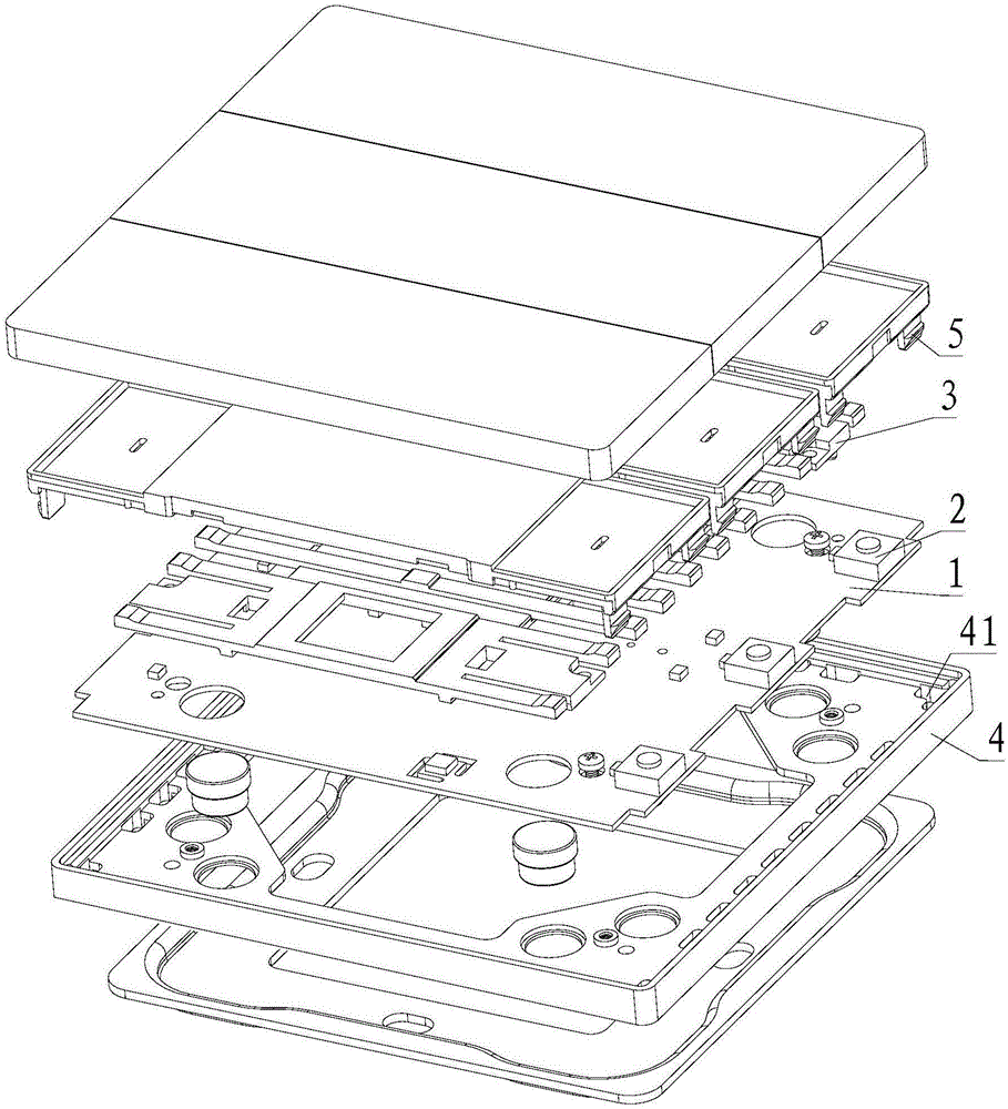
[0047] A switch control panel, on the basis of the second embodiment, further includes a base 4 and a button 5, the base 4 is provided with a through groove 41, and the end of the button 5 is extended downward with a buckle 51, so that The buckle 51 passes through the through groove 41, and is locked on the lower surface of the through groove 41, the circuit board 1 is fixed on the base 4, and the button 5 is located between the micro switch 2 and Above the support body 3, the button 5 is extended downward with a second protrusion 52, the position of the second protrusion 52 corresponds to the position of the first protrusion 34, and the second protrusion 52 is in line with the position of the first protrusion 34. contact with the first protrusion 34, the middle part of the button 5 is extended downward with a second convex strip 53, and the second convex strip 53 is arranged perpen...


PUM


Abstract

The invention provides a switch control panel. The switch control panel comprises a circuit board and a micro-switch, the micro-switch is fixed on the circuit board, the switch control panel further comprises a support body, the support body is fixed on the circuit board and located at the inner side of the micro-switch, and the height of the upper surface of the end portion of the support body is greater than the height of the micro-switch when the micro-switch is pressed and is smaller than the height of the micro-switch when the micro-switch is lifted, wherein the upper surface of the end portion of the support body faces the micro-switch. The upper surface of the end portion of the support body is located between the lowest position of the micro-switch and the highest position of the micro-switch, the support boy can eliminate feeling difference caused by welding errors of the micro-switch, and therefore the consistency of touch feeling is kept when the switch control panel is in use.

Description

technical field [0001] The invention relates to the technical field of switches, in particular to a switch control panel. Background technique [0002] The smart switch control panel is an important part of the smart home. The existing switch control panel is generally based on the size of the traditional panel 86mm*86mm, divided into figure 1 the shape shown, figure 1 The six figures in the figure are respectively the forms when the switch control panel is made to include 1 button, 2 buttons, 3 buttons, 4 buttons, 6 buttons, and 8 buttons. [0003] Existing switch control panel comprises fixed plate 101, magnet 102, base 103, circuit board 104, micro switch 105, key 106 and key cap 107 successively from bottom to top, as figure 2 As shown, the fixed plate 101 is fixed on the wall, the base 103 is adsorbed on the fixed plate 101 by the magnet 102, the circuit board 104 is fixed on the base 103, the micro switch 105 is fixed on the two ends of the circuit board 104, and th...

Claims


Application Information

Patent Timeline
Patent Type & Authority Applications(China)
IPC IPC(8): H01H13/85
CPCH01H13/85H01H2215/024
Inventor 叶滋杰
Owner FUZHOU ONER IND DESIGN CO LTD
Why Eureka
Try Eureka