Lockable power supply device

A technology of power supply device and power supply seat, which is applied in the direction of coupling device, parts of connection device, circuit, etc., can solve problems such as electric shock accident, equipment power failure, equipment failure, etc., achieve high safety, reduce the risk of electric shock, The effect of improving stability

Active Publication Date: 2017-06-13
SUZHOU SHENGXIN OPTOELECTRONICS TECH
View PDF3 Cites 130 Cited by
  • Summary
  • Abstract
  • Description
  • Claims
  • Application Information

AI Technical Summary

Problems solved by technology

[0002] When the electrical equipment needs to be powered on, it is often powered on by inserting the plug into the socket, while the traditional socket allows the plug to be inserted, and at the same time allows the ordinary rod to be inserted. If someone uses an ordinary rod to insert into the socket Electric shock accidents will be caused, and electric shock accidents will cause damage to the human body. Therefore, there are great potential safety hazards in traditional sockets, and traditional sockets rely on elastic force and friction to maintain power supply status. If you kick or touch the plug, it is easy to cause the plug to fall off, causing the device to suddenly lose power, which will cause the device to malfunction and cause losses to the user

Method used


Image

  • Lockable power supply device
  • Lockable power supply device
  • Lockable power supply device

Examples


Embodiment Construction

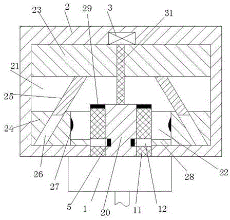
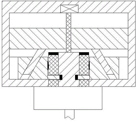
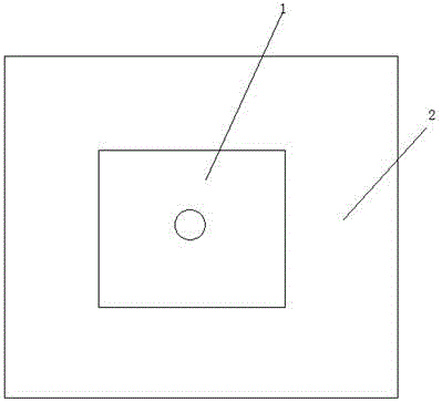
[0014] Combine below Figure 1-3 The present invention will be described in detail.

[0015] refer to Figure 1-3 , a lockable power supply device according to an embodiment of the present invention, comprising a power supply base 2 and a power supply plug 1, the power supply base 2 is provided with a chute 21, and the front end of the chute 21 is also provided with left and right extending The guide groove 22, the left and right symmetrical axis of the guide groove 22 is provided with a partition 20 integrated with the power supply base 2, the front end of the power supply base 2 is symmetrically provided with slots, and the slots extend to the rear end To the rear end wall of the guide groove, a slider 23 is installed in the slide groove 21 to slide back and forth, and a guide block 24 is installed in the guide groove 22 to slide left and right, and the guide block 24 faces the insertion The end face of the groove is provided with a locking arm 28 and a conductive contact ...


PUM


Abstract

The invention provides a lockable power supply device. The lockable power supply device includes a power supply base and a power supply plug. A slide chute is arranged in the power supply base. The front end of the slide chute is also provided with a guide groove extending left and right. A partition formed integrally with the power supply base is arranged at the vertical axis of symmetry of the guide groove. A slot is arranged in the front end of the power supply base in a vertically symmetric manner. A slide block is mounted in the slide chute in a manner of sliding forward and backward. A guide block is mounted in the guide groove in a manner of sliding left and right. An end face of the guide block facing the slot is provided with a locking arm and a conducting contact. The conducting contact is disposed at the rear end of the locking arm. The guide block is therein provided with a through groove. A screw rod is mounted in the slide block. The front end of the screw rod is mounted in the partition in a rotary manner. The rear end of the screw rod is in power connection with a motor mounted in the power supply based. The rear end face of the power supply plug is provided with a conducting inserting rod. The conducting inserting rod is therein provided with a locking groove fitting with the locking arm. The power supply device provided by the invention is high in safety performance. During the power supply process, the conducting inserting rod can be locked. Therefore, the power supply stability is improved substantially.

Description

technical field [0001] The invention relates to the field of electric power supply, in particular to a lockable power supply device. Background technique [0002] When the electrical equipment needs to be powered on, it is often powered on by inserting the plug into the socket, while the traditional socket allows the plug to be inserted, and at the same time allows the ordinary rod to be inserted. If someone uses an ordinary rod to insert into the socket Electric shock accidents will cause electric shock accidents, and electric shock accidents will cause damage to the human body. Therefore, traditional sockets have great potential safety hazards, and traditional sockets rely on elastic force and friction to maintain power supply status. Kicking or bumping into the plug will easily cause the plug to fall, causing the device to suddenly lose power, which will cause the device to malfunction and cause losses to the user. Contents of the invention [0003] The object of the p...

Claims


Application Information

Patent Timeline
Patent Type & Authority Applications(China)
IPC IPC(8): H01R13/639H01R13/629H01R13/70
CPCH01R13/629H01R13/639H01R13/70
Inventor 陆佳浩
Owner SUZHOU SHENGXIN OPTOELECTRONICS TECH
Why Eureka
Try Eureka