
Fault Diagnosis Method for Abnormal Vibration of Rotor Caused by Floating Oil Gear

A fault diagnosis and floating technology, applied in the testing of mechanical components, testing of machine/structural components, instruments, etc., can solve problems such as difficult fault diagnosis and achieve fast and accurate diagnosis results

Active Publication Date: 2019-06-04
SHANDONG ZHONGSHI YITONG GRP
View PDF7 Cites 0 Cited by
  • Summary
  • Abstract
  • Description
  • Claims
  • Application Information

AI Technical Summary

Problems solved by technology

At present, there are few practical applications, and there are few cases of abnormal vibration faults caused by floating oil gears, which often bring certain difficulties to fault diagnosis

Method used


Image

  • Fault Diagnosis Method for Abnormal Vibration of Rotor Caused by Floating Oil Gear
  • Fault Diagnosis Method for Abnormal Vibration of Rotor Caused by Floating Oil Gear

Examples


Embodiment Construction

[0026] The present invention will be further described below in conjunction with the accompanying drawings and embodiments.

[0027] It should be pointed out that the following detailed description is exemplary and intended to provide further explanation to the present application. Unless defined otherwise, all technical and scientific terms used herein have the same meaning as commonly understood by one of ordinary skill in the art to which this application belongs.

[0028] It should be noted that the terminology used here is only for describing specific implementations, and is not intended to limit the exemplary implementations according to the present application. As used herein, unless the context clearly dictates otherwise, the singular is intended to include the plural, and it should also be understood that when the terms "comprising" and / or "comprising" are used in this specification, they mean There are features, steps, operations, means, components and / or combinatio...


PUM


Abstract

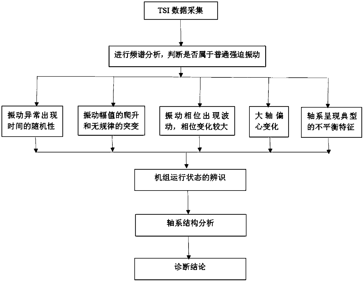
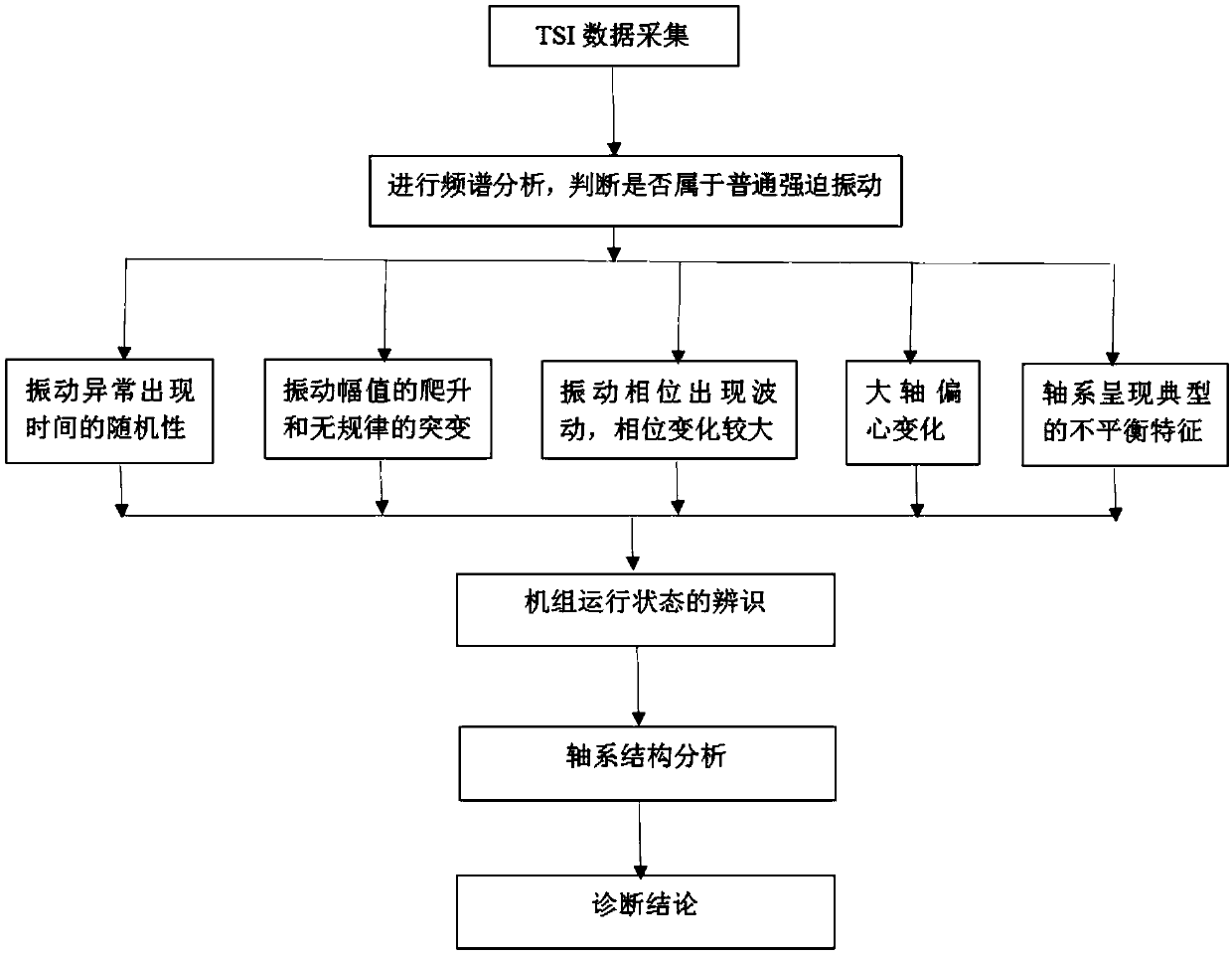
The invention discloses a fault diagnosis method of abnormal vibration, of a rotor, caused by a floating oil retainer. The fault diagnosis method of abnormal vibration, of a rotor, caused by a floating oil retainer includes the steps: importing shafting TSI data into a fault diagnosis system; setting a threshold, utilizing a spectrum analysis method, determining whether the property of shafting abnormity vibration belongs to common forced vibration, extracting typical characteristics of a fault, analyzing operating parameters of a set, and eliminating the influence of load, thermal deformation and field current; and with combination of shafting structure analysis structure, determining whether abnormal vibration of the rotor is caused by a floating oil retainer, and then obtaining a diagnosis result. The fault diagnosis method of abnormal vibration, of a rotor, caused by a floating oil retainer has the advantages of being comprehensive in the considered extracted characteristics, being suitable for field fault diagnosis, being quick and accurate in result diagnosis, and having practicality and operability.

Description

technical field [0001] The invention relates to a fault diagnosis method for abnormal vibration of a rotor caused by a floating oil gear. Background technique [0002] The floating oil gear of the turbogenerator is a new type of oil gear. Compared with the traditional fixed oil gear, it can change with the position of the rotor to a certain extent, and always follow the rotor. Theoretically, there will be no gap. Uniform and oil leakage. At present, there are few practical applications, and there are few cases of abnormal vibration faults caused by floating oil gears, which often bring certain difficulties to fault diagnosis. Contents of the invention [0003] In order to solve the above problems, the present invention proposes a fault diagnosis method for abnormal vibration of the rotor caused by the floating oil gear. The present invention uses typical data as the analysis basis, and has typicality, practicability and operability. [0004] In order to achieve the above...

Claims


Application Information

Patent Timeline
Patent Type & Authority Patents(China)
IPC IPC(8): G01M13/00
CPCG01M13/00
Inventor 张善鹏张杰邢秀苹邓文俭毕仲波许怀志刘浩
Owner SHANDONG ZHONGSHI YITONG GRP
Learn More