Supercharge Your Innovation With Domain-Expert AI Agents!

A backside observation base for positioning in chip failure analysis and using method

A failure analysis and positioning method technology, which is applied in the direction of instruments, measuring devices, electronic circuit testing, etc., can solve problems such as troublesome analysis work and difficult precise positioning, and achieve the effect of accurate conversion, positioning speed and accuracy rate improvement

Active Publication Date: 2019-07-12
HEJIAN TECH SUZHOU
View PDF5 Cites 0 Cited by
  • Summary
  • Abstract
  • Description
  • Claims
  • Application Information

AI Technical Summary

Problems solved by technology

When there is no special pattern around, or the difference between the front metal layer image and the layout of the complex crystal & active layer is too large, it is difficult to accurately locate and only roughly determine the failure location, which causes great trouble for subsequent analysis.

Method used


Image

  • A backside observation base for positioning in chip failure analysis and using method
  • A backside observation base for positioning in chip failure analysis and using method
  • A backside observation base for positioning in chip failure analysis and using method

Examples


Embodiment Construction

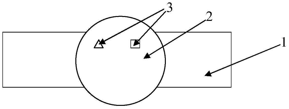
[0025] Such as figure 1 As shown, the rear viewing base used for accurate positioning in chip failure analysis of the present invention includes a metal support 1 , a central hole is provided in the center of the metal support 1 , and a glass plate 2 is installed in the central hole. Two special marks 3 of a triangle and a rectangle for providing reference coordinates have been etched on the glass sheet 2, any one of these two special marks 3 can be set as mark point A, and the other can be set as mark point B . In addition, the special mark 3 may be etched before the analysis, or temporarily pasted on the glass slide 2 during the analysis. The metal support 1 of the rear viewing base can be any metal material with a certain strength and can bear a certain load. Since the weight of the wafer carried is very small, its material is not particularly limited, but considering the economical properties and strength, it is preferably stainless steel.

[0026] The glass sheet 2 arr...


PUM


Abstract

The invention provides a rear observation base for precise positioning in chip failure analysis, which includes a metal bracket, a center hole is arranged in the center of the metal bracket, a glass sheet is installed in the center hole, and a There are also two special marks for providing reference coordinates on the sheet. The two special marks are etched or pasted on the glass sheet. The position is any position on the glass sheet of the rear viewing base and can be Set to the same or different shape. Therefore, in the failure analysis analysis, when PEM / OBIRCH uses the back mode to locate the abnormal point, it can accurately find and record the position of the abnormal point at the front position. The invention also relates to a method for precise positioning in chip failure analysis by using the backside viewing base.

Description

technical field [0001] The invention relates to a backside observation base, in particular to a backside observation base used for precise positioning in chip failure analysis. The invention also relates to a method for precise positioning in chip failure analysis by using the backside viewing base. Background technique [0002] In the field of semiconductor manufacturing, with the development of IC manufacturing process to small size and multi-level, in order to improve the accuracy of failure analysis in chip failure (FA) analysis, PEM (photo emission microscope, photon emission microscope) / OBIRCH (optical beam Induced resistance change (beam-induced impedance value change test) is used more and more to locate the failure position of the chip by using the backside positioning method. [0003] However, when the wafer is positioned using the backside positioning method, it is not possible to directly use a laser marker (laser marker) to mark the position of the detected a...

Claims


Application Information

Patent Timeline
Patent Type & Authority Patents(China)
IPC IPC(8): G01R31/28G01R1/04
CPCG01R1/04G01R31/2851
Inventor 宋朝刚孔亮李少帅翟海雷
Owner HEJIAN TECH SUZHOU
Features
  • R&D
  • Intellectual Property
  • Life Sciences
  • Materials
  • Tech Scout
  • Unparalleled Data Quality
  • Higher Quality Content
  • 60% Fewer Hallucinations
Learn More