Bridge equipment

A technology for equipment and bridges, applied in the field of bridge equipment, can solve the problems of inconvenient retraction and release of power supply lines of wiring boards, increased use costs, and difficulties in power supply connection, etc. simple effect

Active Publication Date: 2017-06-30
浦江晨风新材料科技有限公司
View PDF5 Cites 7 Cited by
  • Summary
  • Abstract
  • Description
  • Claims
  • Application Information

AI Technical Summary

Problems solved by technology

[0002] Electrified maintenance equipment is often used in the bridge maintenance process. However, in some bridge constructions, there are fewer preset power supply seats and they are all fixed, which makes some bridge maintenance equipment in maintenance because the maintenance parts are far from the power supply seats This makes it difficult to connect the power supply. In the prior art, one or more terminal boards are generally used to lengthen the connection to reach the ideal power supply insertion length. However, the operation of this power supply mode is too complicated and the power supply line of the terminal board is too long. It is extremely inconvenient to release. There are also some bridge power supply equipment that can automatically take up the line, but they need to be connected to the mains to work, which increases the cost of use and seriously wastes power resources. There are major drawbacks and need to be improved.

Method used


Image

  • Bridge equipment
  • Bridge equipment
  • Bridge equipment

Examples


Embodiment Construction

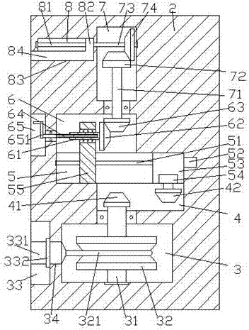
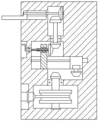
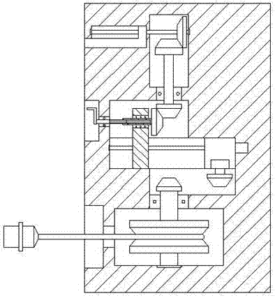
[0019] Such as Figure 1-Figure 5 As shown, a bridge device of the present invention includes a body 2, a slide groove 5 is provided at the center of the inside of the body 2, and a first empty groove 6 is provided in the body 2 above the left side of the slide groove 5, The body 2 below the right side of the sliding groove 5 is provided with a second empty groove 4, and the body 2 at the bottom of the second empty groove 4 is provided with an accommodation groove 3, and the right side of the first empty groove 6 A power transmission cavity 7 is arranged on the upper side, and a first screw rod 51 is arranged in the sliding groove 5, and the right end of the first screw rod 51 is connected with the first driving machine 52, and the upper screw rod 51 is screwed. The vertical rod 55 extending upwards and the sliding block 53 arranged on the right side of the vertical rod 55 are connected by thread fit. The upward extending section of the vertical rod 55 extends into the first e...


PUM


Abstract

The invention discloses bridge equipment. The bridge equipment comprises a machine body, wherein a sliding groove is formed at the center inside the machine body; a first empty groove is formed in the machine body above the left side of the sliding groove; a second empty groove is formed in the machine body below the right side of the sliding groove; a containing groove is formed in the machine body at the bottom of the second empty groove; a force transmission chamber is arranged above the right side of the first empty groove; the sliding groove is internally provided with a first screw rod; the right end of the first screw rod is connected with a first driving machine; a spiral thread on the first screw rod is matched and connected with a vertical rod which extends upward and a sliding block arranged on the right side of the vertical rod; an upward extending section of the vertical rod stretches into the first empty groove and the inner part of the vertical rod is rotatably matched and connected with an inner spline shaft; a first gear is fixedly arranged on the right end of the inner spline shaft; the inner part of the inner spline shaft is matched and connected with an outer spline shaft; and a second gear is engaged and connected with the upper side of the right side of the first gear. The bridge equipment disclosed by the invention is simple in structure and convenient to operate; automatic take-up work can be realized and the bridge equipment has a rain-proof function; and the working efficiency is improved, wastes of electric supply are reduced and the utilization cost is relatively low, so that the bridge equipment is suitable for popularization and application.

Description

technical field [0001] The invention relates to the technical field of bridge facilities, in particular to bridge equipment. Background technique [0002] Electrified maintenance equipment is often used in the bridge maintenance process. However, in some bridge constructions, there are fewer preset power supply seats and they are all fixed. This makes it difficult to connect the power supply. In the prior art, one or more terminal boards are generally used to lengthen the connection to reach the ideal power supply insertion length. It is extremely inconvenient to put it on, and there are some bridge power supply equipment that can automatically take up the line in the existing ones, but they need to be connected to the mains, which increases the cost of use and seriously wastes power resources. There are major drawbacks and need to be improved. Contents of the invention [0003] The technical problem to be solved by the present invention is to provide a bridge device, whi...

Claims


Application Information

Patent Timeline
Patent Type & Authority Applications(China)
IPC IPC(8): E01D22/00H02G11/02
CPCE01D22/00H02G11/02
Inventor 甘路
Owner 浦江晨风新材料科技有限公司
Why Eureka
Try Eureka