Novel new energy vehicle charging device

A new energy vehicle and charging device technology, which is applied in electric vehicle charging technology, charging stations, electric vehicles, etc., can solve the problems of charging piles that do not have automatic winding wires, accidents, and shortening of wire life, so as to improve the winding speed. Efficiency and stability, reduction of utility power waste, and easy operation

Inactive Publication Date: 2017-10-13
义乌市源德进出口有限公司
View PDF0 Cites 2 Cited by
  • Summary
  • Abstract
  • Description
  • Claims
  • Application Information

AI Technical Summary

Problems solved by technology

[0003] The existing charging piles need to manually put the charging cable back into the charging pile after the charging is completed, but the charging wire is generally long, which brings great inconvenience to the user, and the current charging pile does not have automatic winding The function of the wire, the user often does not place the wire according to the requirements after use, but throws the wire on the ground at will; in this way, the wire is vulnerable to various unexpected stresses, such as people trampling on it, cars running over it, etc., resulting in the outer insulation of the wire Damage, resulting in reduced life of the wire, resulting in accidents such as electric shock

Method used


Image

  • Novel new energy vehicle charging device
  • Novel new energy vehicle charging device
  • Novel new energy vehicle charging device

Examples


Embodiment Construction

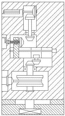
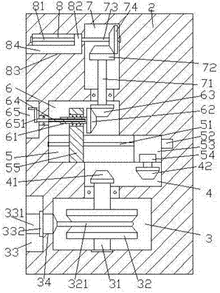
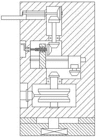
[0021] Such as Figure 1-Figure 5 As shown, a new type of new energy vehicle charging device of the present invention includes a charging pile body 2, and a sliding groove 5 is horizontally arranged at the middle position inside the charging pile body 2, and the charging device on the upper left side of the sliding groove 5 A first cavity 6 is provided in the pile body 2, a second cavity 4 is provided in the charging pile body 2 below the right side of the sliding groove 5, and a second cavity 4 is arranged in the charging pile body at the bottom of the second cavity body 4 2 is provided with a take-up cavity 3, the upper right side of the first cavity 6 is provided with a transmission cavity 7, the sliding groove 5 is provided with a first screw 51, and the right end of the first screw 51 is connected to the first The motor 52 is power connected, and the first screw rod 51 is threadedly connected with an upwardly extending moving rod 55 and a moving block 53 arranged on the r...


PUM


Abstract

The invention discloses a novel new energy vehicle charging device, comprising a charging pile body. The middle position in the charging pile body is horizontally provided with a sliding groove. A first cavity is arranged in the charging pile body on the left upper part of the sliding groove. A second cavity is arranged in the charging pile body on the right lower part of the sliding groove. A take-up cavity is arranged in the charging pile body on the bottom of the second cavity. A transmission cavity is arranged on the right side upper part of the first cavity. A first screw rod is arranged in the sliding groove. The right side end of the first screw rod is connected with a first motor by power. The first screw rod is connected with a moving rod extending upward by thread cooperation, and a moving block arranged on the right side of the moving rod. The upward extending segment of the moving rod extends into the first cavity and is internally rotatably connected with a female splined shaft in a cooperation manner. The right side end of the female splined shaft is fixedly provided with a first cone wheel. The female splined shaft is internally connected with a male splined shaft in a cooperation manner. The right side upper part of the first cone wheel is meshed with a second cone wheel. The device is simple in structure and convenient in operation, and prevents rainwater from falling into the charging pile body, so as to improve working efficiency and security.

Description

technical field [0001] The invention relates to the technical field of new energy vehicle charging, in particular to a novel new energy vehicle charging device. Background technique [0002] At present, energy saving, environmental protection, and low-carbon life are hot topics. In order to achieve the goal of emission reduction, the country vigorously promotes electric vehicles. Electric vehicles do not emit carbon dioxide and have no tail gas pollution. They are very beneficial for controlling environmental pollution and reducing tail gas emissions, and electricity can be obtained through a variety of energy sources, such as thermal power, hydropower, nuclear power, wind power and solar power. [0003] The existing charging piles need to manually put the charging cable back into the charging pile after the charging is completed, but the charging wire is generally long, which brings great inconvenience to the user, and the current charging pile does not have automatic windi...

Claims


Application Information

Patent Timeline
IPC IPC(8): B60L11/18
CPCB60L53/31Y02T10/70Y02T10/7072Y02T90/12
Inventor 蒋杨进
Owner 义乌市源德进出口有限公司
Why Eureka
Try Eureka