Inserting and dismounting type ventilation window

A ventilation window and screen window technology, which is applied to windows/doors, door/window protection devices, insect protection, etc., can solve the problems of inconvenient cleaning, reduced service life of transformers, and large load loss, etc., and achieves convenient cleaning, reliable installation, and quick disassembly Effect

Inactive Publication Date: 2017-06-30
DEYANG YIYOU METALLURGICAL EQUIP MFG CO LTD
View PDF0 Cites 0 Cited by
  • Summary
  • Abstract
  • Description
  • Claims
  • Application Information

AI Technical Summary

Problems solved by technology

[0002] At present, poor heat dissipation and ventilation in equipment rooms such as transformer rooms in urban substations is a common problem. There are many reasons. When running at full load, the load loss is the largest. The heat generated by these losses depends on the natural circulation of insulating oil, and dissipates heat to the transformer room through the radiator and body shell of the transformer. The heat in the room can only be obtained by convection of the indoor air The ventilation window is brought outdoors to meet the environmental requirements of the transformer during operation. Although the ventilation window is equipped with dust-proof measures, the dust-proof effect of the screen window will decrease significantly after a long time, and the heat dissipation and ventilation effect of the ventilation window will be greatly affected. Since most of the current ventilation windows are integrally installed ventilation windows, it is difficult to disassemble and not easy to clean. During the summer peak load period of many substations, due to poor ventilation, the temperature of the transformer operating environment is too high and the temperature of the upper oil layer of the transformer is too high. , affecting the reliability of power supply and reducing the service life of the transformer, the existing integrated ventilation window can no longer meet the needs of the transformer operation

Method used


Image

  • Inserting and dismounting type ventilation window
  • Inserting and dismounting type ventilation window
  • Inserting and dismounting type ventilation window

Examples


Embodiment 1

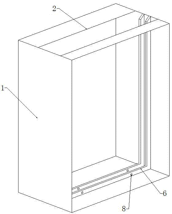
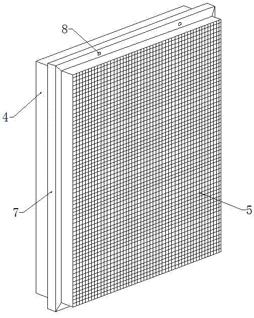
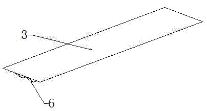
[0015] A detachable ventilation window, comprising a frame 1 and a screen window 4, the top of the frame 1 is provided with an opening 2, the opening 2 is provided with a cover plate 3, and the inside of the frame 1 and the lower end of the cover plate 3 are respectively provided with Clamping groove 6 is used to block the protruding strip 7 to prevent the screen window 4 from moving easily, etc. The outside of the screen window 4 is provided with a dust-proof net 5 to prevent dust such as dust from entering the equipment room, and the screen window 4 is provided with protruding strips 7 around , for installation in the clamping groove 6, the convex strip 7 is matched with the clamping groove 6, the clamping groove 6 at the bottom of the frame 1, the clamping groove 6 on the cover plate 3 and the convex strips 7 at the upper and lower ends of the screen window 4 Screw holes 8 are respectively provided for fixing the screen window 4 and the cover plate 3 by bolts.


PUM


Abstract

The invention relates to an inserting and dismounting type ventilation window which comprises a frame and a screen window body. The top end of the frame is provided with an opening which is provided with a cover plate. Clamping grooves are separately formed in the frame and in the lower end of the cover plate. The outer side of the screen window body is provided with a dust screen body. The periphery of the screen window body is provided with convex strips which are matched with the clamping grooves. The clamping grooves in the bottom end of the frame, the clamping groove in the cover plate and the convex strips at the upper end and the lower end of the screen window body are separately provided with screw holes. The inserting and dismounting type ventilation window has the beneficial effects that by arranging the inserting and dismounting type screen window body, the inserting and dismounting type ventilation window can be rapidly dismounted, is firm, reliable and quite convenient to clean, has the ventilation effect, the small animal prevention effect and the like and is firm in mounting.

Description

technical field [0001] The invention relates to a ventilation device, in particular to a detachable ventilation window. Background technique [0002] At present, poor heat dissipation and ventilation in equipment rooms such as transformer rooms in urban substations is a common problem. There are many reasons. When running at full load, the load loss is the largest. The heat generated by these losses depends on the natural circulation of insulating oil, and dissipates heat to the transformer room through the radiator and body shell of the transformer. The heat in the room can only be obtained by convection of the indoor air The ventilation window is brought outdoors to meet the environmental requirements of the transformer during operation. Although the ventilation window is equipped with dust-proof measures, the dust-proof effect of the screen window will decrease significantly after a long time, and the heat dissipation and ventilation effect of the ventilation window will ...

Claims


Application Information

Patent Timeline
Patent Type & Authority Applications(China)
IPC IPC(8): E06B9/52
CPCE06B9/52E06B2009/527
Inventor 曹祖林冯军
Owner DEYANG YIYOU METALLURGICAL EQUIP MFG CO LTD
Why Eureka
Try Eureka