[0030] The embodiments of the present invention are described in detail below. Examples of the embodiments are shown in the accompanying drawings, in which the same or similar reference numerals indicate the same or similar elements or elements with the same or similar functions. The embodiments described below with reference to the accompanying drawings are exemplary, and are intended to explain the present invention, but should not be construed as limiting the present invention.
[0031] In the description of the present invention, it should be understood that the terms "center", "longitudinal", "upper", "lower", "front", "rear", "left", "right", "vertical", " The orientation or positional relationship indicated by “horizontal”, “inner”, “outer”, and “circumferential” is based on the orientation or positional relationship shown in the drawings, and is only for the convenience of describing the present invention and simplifying the description, rather than indicating or implying what is meant. The device or element must have a specific orientation, be constructed and operated in a specific orientation, and therefore cannot be understood as a limitation of the present invention. In addition, the features defined with "first" and "second" may explicitly or implicitly include one or more of these features. In the description of the present invention, unless otherwise specified, "plurality" means two or more.
[0032] In the description of the present invention, it should be noted that the terms "installation", "connected" and "connected" should be understood in a broad sense, unless otherwise clearly specified and limited. For example, they can be fixed or detachable. Connected or integrally connected; it can be a mechanical connection or an electrical connection; it can be directly connected or indirectly connected through an intermediate medium, and it can be the internal communication between two components. For those of ordinary skill in the art, the specific meanings of the above-mentioned terms in the present invention can be understood in specific situations.
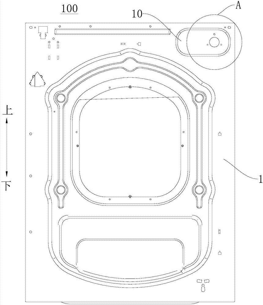
[0033] Combine below Figure 1 to Figure 7 The washing machine 100 according to an embodiment of the present invention is described in detail.
[0034] The washing machine 100 according to the embodiment of the present invention includes: a cabinet 1 and a water inlet valve 2.
[0035] Specifically, the box body 1 has a water inlet valve mounting plate 10 arranged vertically. For example, the box body 1 has a water inlet valve mounting plate 10 arranged along the vertical plane where the vertical direction and the left and right directions are located, and the water inlet valve 2 is easily installed on the box body 1 through the water inlet valve mounting plate 10.
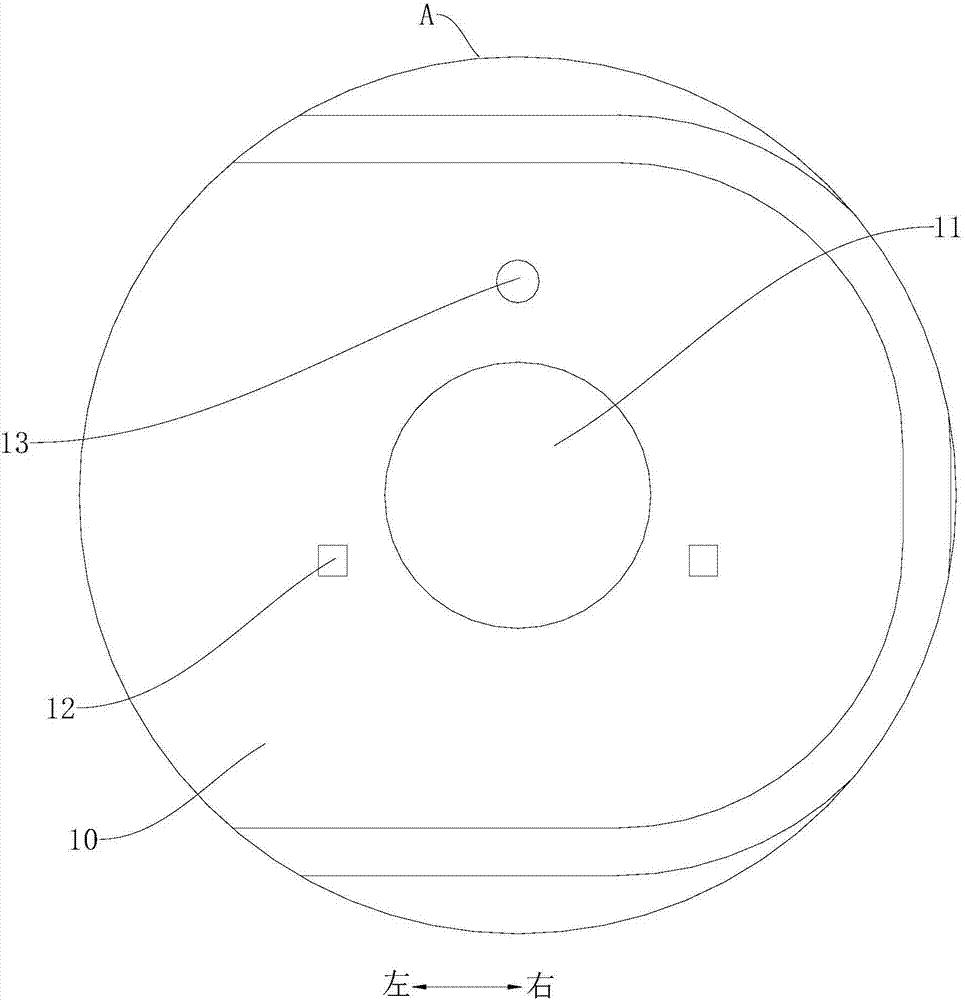
[0036] The inlet valve mounting plate 10 has a mounting hole 11 and a first slot 12 and a second slot 13 adjacent to the mounting hole 11. Therefore, the installation of the water inlet valve 2 on the box 1 can be further realized through the installation hole 11, the first slot 12 and the second slot 13.
[0037] The water inlet valve 2 is installed on the water inlet valve mounting plate 10 and the water inlet 21 of the water inlet valve 2 passes through the mounting hole 11. In other words, the water inlet valve 2 is installed on the water inlet valve mounting plate 10, and the water inlet 21 of the water inlet valve 2 can pass through the mounting hole 11. By passing the water inlet 21 of the water inlet valve 2 through the mounting hole 11, the water inlet valve 2 can be positioned on the box body 1, which facilitates the installation of the water inlet valve 2 on the box body 1.
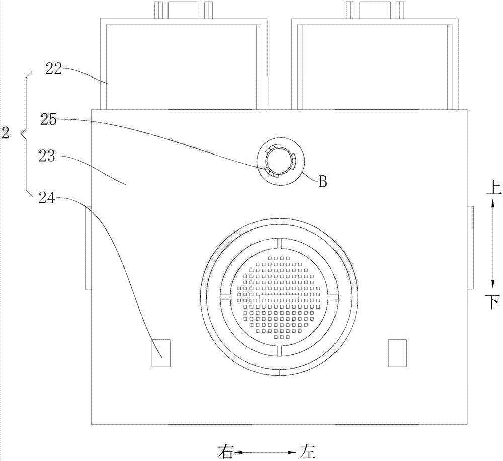
[0038] The water inlet valve 2 includes a valve body 22, a positioning plate 23 and a first buckle 24 and a second buckle 25 provided on the positioning plate 23. In other words, the water inlet valve 2 includes a valve body 22, a positioning plate 23, a first buckle 24 and a second buckle 25, and the first buckle 24 and the second buckle 25 can be provided on the positioning plate 23. The first buckle 24 passes through the first groove 12 to engage with the box body 1, and the second buckle 25 passes through the second groove 13 to engage with the box body 1. Thus, by allowing the first buckle 24 to pass through the first slot 12 to engage with the box body 1, and the second buckle 25 to pass through the second slot 13 to engage with the box body 1, the water inlet valve 2 can be further It is fixed on the box body 1, so as to realize the reliable installation of the water inlet valve 2 on the box body 1, without using external tools, and simple operation.
[0039] According to the washing machine 100 of the embodiment of the present invention, the water inlet 21 of the water inlet valve 2 passes through the mounting hole 11, and the first buckle 24 passes through the first groove 12 to engage with the cabinet 1, and the second buckle 25 passes through the second slot 13 to be engaged with the box body 1 to realize the reliable installation of the water inlet valve 2 on the box body 1, without screwing and without external tools, which can be completed manually, and the operation is simple.
[0040] Reference Figure 7 And combine Figure 5 According to the washing machine 100 of the embodiment of the present invention, the first buckle 24 is L-shaped, and the first buckle 24 includes: a first branch 241 and a second branch 242, the first branch 241 is connected to the positioning plate 23, and the first branch 241 is perpendicular to the positioning plate 23; the free ends of the second branch 242 and the first branch 241 (refer to Figure 7 The rear end of the first branch 241) is connected, and the second branch 242 is parallel to the positioning plate 23. Therefore, the structure of the first buckle 24 is simple, easy to manufacture, and it is convenient to cooperate with the first buckle 24 and the first groove 12, which is advantageous for further realizing the reliable installation of the water inlet valve 2 on the box body 1. condition.
[0041] The present invention is not limited to this, and the first buckle 24 may also have other structural forms such as U-shaped.
[0042] Further, combine Figure 5 with Figure 7 , The free ends of the second branch 242 and the first branch 241 (refer to Figure 7 The rear end of the first branch 241) is connected and downward (refer to Figure 7 Shown in below) extension. In other words, the second branch 242 is connected to the free end of the first branch 241, and the second branch 242 may extend downward. This facilitates the engagement of the second support portion 242 at the first slot 12 and helps ensure the reliability of the connection between the first buckle 24 and the box 1.
[0043] Specifically, refer to image 3 , The first buckle 24 includes the left and right directions (refer to image 3 The left and right directions shown in) are arranged at intervals. In other words, the first buckle 24 includes multiple (two, three, four, etc.), and the multiple first buckles 24 can be image 3 Spaced in the left and right directions shown in The force can be balanced by the multiple first buckles 24, which is beneficial to ensure the installation reliability of the water inlet valve 2 on the box body 1.
[0044] For example, in image 3 In the illustrated embodiment of the present invention, the first buckle 24 may include two buckles arranged at intervals along the left-right direction of the positioning plate 23. The number and arrangement of the first buckles 24 can be set as required.
[0045] Optionally, refer to image 3 , Figure 4 as well as Image 6 , The second buckle 25 includes: a positioning column 251, the positioning column 251 is connected to the positioning plate 23, and the positioning column 251 is perpendicular to the positioning plate 23, the peripheral surface of the free end of the positioning column 251 is provided with a hook 252, the hook 252 and the positioning The plates 23 are separated by a predetermined distance. In the process of engaging the second buckle 25 with the second groove 13, the positioning post 251 can play a certain guiding role. By separating the hook 252 from the positioning plate 23 by a predetermined distance, it can be the water inlet valve 2. The installation of ”provides escape space, and the inlet valve 2 can be reliably installed on the box body 1 through the second buckle 25.
[0046] Among them, combined Figure 4 The hook portion 252 may include a plurality of hook portions 252, and the plurality of hook portions 252 may be evenly spaced and arranged around the positioning pillar 251. E.g, Figure 4 Three hooks 252 are shown in the figure. The three hooks 252 can be arranged evenly spaced around the positioning column 251. The specific number and arrangement of the hooks 252 can be adapted according to actual needs.
[0047] Further, refer to Figure 5 with Image 6 , In the direction toward the positioning plate 23 (refer to Figure 5 The direction from the rear to the front shown in the figure), the height of the hook 252 protruding from the peripheral surface of the positioning post 251 gradually increases. For example, the hook portion 252 can be wedge-shaped, so that during the engagement of the second buckle 25 with the second slot 13, the hook portion 252 can not only play a certain guiding role, but also limit the position, which is beneficial to improve the access Reliable installation of water valve 2 on box 1.
[0048] Optionally, refer to figure 2 with image 3 , The second buckle 25 and the first buckle 24 are in the up and down direction (refer to image 3 The upper and lower directions shown in the figure are spaced apart, the first slot 12 may be square, and the second slot 13 may be circular. As a result, it is convenient for the first buckle 24 to pass through the first groove 12 to engage with the box body 1, and the second buckle 25 to pass through the second groove 13 to engage with the box body 1, thereby realizing the water inlet valve 2 Reliable installation on the box 1.
[0049] Among them, the first slot 12 is square, and the second slot 13 is circular. This makes the first card slot 12 and the second card slot 13 easy to manufacture, which is beneficial to reduce costs.
[0050] In some embodiments of the present invention, reference image 3 The first buckle 24 includes a plurality of buckles arranged at intervals in the horizontal direction, and the second buckle 25 is arranged at a position higher or lower than the first buckle 24. In other words, the first buckle 24 includes a plurality, and the plurality of first buckles 24 may be arranged at intervals in the horizontal direction, and the second buckle 25 is arranged at a position higher or lower than the first buckle 24. The horizontal direction here can refer to image 3 Any direction in the longitudinal plane where the up and down direction and the left and right direction are shown in the figure; here higher or lower refers to the relative height of the second buckle 25 and the first buckle 24 in the up and down direction along the positioning plate 23 position.
[0051] For example, in figure 2 Among them, the first card slot 12 can include two, and the two first card slots 12 can be arranged at intervals along the left and right direction; the second card slot 13 includes one, and two first card slots 12 and one second card slot 13 The water inlet valve mounting plate 10 can be arranged in a triangle shape.
[0052] in image 3 Among them, the first buckle 24 includes two, the two first buckles 24 can be arranged at the lower part of the water inlet valve 2, and the two first buckles 24 are spaced apart in the left-right direction; the second buckle 25 includes The setting position of one and one second buckle 25 can be higher than the setting position of the two first buckles 24, and the two first buckles 24 and one second buckle 25 can be arranged in a triangle on the water inlet valve 2 .
[0053] By making the water inlet 21 of the water inlet valve 2 pass through the mounting hole 11, the first buckle 24 passes through the first groove 12 to engage with the box 1, and the second buckle 25 passes through the second groove 13 and The box body 1 is locked, which can realize the reliable installation of the water inlet valve 2 on the box body 1, and can ensure the stability of the installation, without the use of external tools, and the operation is simple.
[0054] In some embodiments of the present invention, both the first buckle 24 and the second buckle 25 are integrally formed with the positioning plate 23 or connected by welding. In other words, the first buckle 24 and the second buckle 25 are integrally formed with the positioning plate 23, or the first buckle 24 and the second buckle 25 are both welded and connected to the positioning plate 23. As a result, the processing technology can be simplified, the cost can be reduced, and the number of parts can be reduced, and the assembly is easy.
[0055] Optionally, refer to image 3 The first buckle 24 and the second buckle 25 are arranged at intervals in a direction surrounding the water inlet 21 (for example, the water inlet 21 of the water inlet valve 2). In the process of assembling the water inlet valve 2 with the box body 1, it is convenient for the water inlet 21 of the water inlet valve 2 to pass through the mounting hole 11, and the first buckle 24 to pass through the first slot 12 to engage with the box body 1. The second buckle 25 passes through the second slot 13 to be engaged with the box body 1, which is easy to realize the reliable installation of the water inlet valve 2 on the box body 1, and the operation is convenient and quick.
[0056] In some embodiments of the present invention, the positioning plate 23 is attached to the inlet valve mounting plate 10. Therefore, the reliability of the connection between the water inlet valve 2 and the box body 1 can be ensured, and the sealing between the water inlet valve 2 and the box body 1 can be ensured, and water leakage can be effectively prevented; in addition, the appearance of the washing machine 100 is beautiful .
[0057] Combine below Figure 1 to Figure 7 The working process of the washing machine 100 according to the embodiment of the present invention is described in detail.
[0058] Specifically, the water inlet valve 2 includes a water inlet 21, a valve body 22, a positioning plate 23, a first buckle 24 and two second buckles 25. There are two types of buckles on the water inlet valve 2, a first buckle 24 and a second buckle 25. The first buckle 24 is roughly cylindrical, and three small buckles (the aforementioned hook 252), the second buckle 25 is an L-shaped baffle; the box body 1 is formed with a first card slot 12 and a second card slot 13, the first card slot 12 is square, and the second card slot 13 is round.
[0059] A mounting hole 11, a first slot 12 and a second slot 13 are provided on the inlet valve mounting plate 10 on the box body 1. The diameter of the mounting hole 11 is larger than the diameter of the water inlet 21 of the water inlet valve 2, which reduces the difficulty of assembly and is easy to assemble. The first slot 12 is circular, the first slot 12 is matched with the first buckle 24, the second slot 13 is square, and the second slot 13 is matched with the second buckle 25. The water inlet 21 of the water inlet valve 2 passes through the mounting hole 11, the second buckle 25 is matched with the second groove 13, and the first buckle 24 is pressed into the first groove 12, and the water inlet valve 2 is sufficient Stably fixed on the box 1.
[0060] By making the water inlet 21 of the water inlet valve 2 pass through the mounting hole 11, the first buckle 24 passes through the first groove 12 to engage with the box 1, and the second buckle 25 passes through the second groove 13 and The box body 1 is locked, which can realize the reliable installation of the water inlet valve 2 on the box body 1, and can ensure the stability of the installation, without the use of external tools, and the operation is simple. So far, the working process of the washing machine 100 according to the embodiment of the present invention is completed.
[0061] Other components and operations of the washing machine 100 according to the embodiment of the present invention are known to those of ordinary skill in the art, and will not be described in detail here.
[0062] In the description of this specification, descriptions with reference to the terms "one embodiment", "some embodiments", "examples", "specific examples" or "some examples" etc. mean specific features described in conjunction with the embodiment or example, The structure, material or feature is included in at least one embodiment or example of the present invention. In this specification, the schematic representations of the above-mentioned terms do not necessarily refer to the same embodiment or example. Moreover, the described specific features, structures, materials or characteristics can be combined in any one or more embodiments or examples in a suitable manner. In addition, those skilled in the art can combine and combine the different embodiments or examples and the characteristics of the different embodiments or examples described in this specification without contradicting each other.
[0063] Although the embodiments of the present invention have been shown and described above, it can be understood that the above embodiments are exemplary and should not be construed as limiting the present invention. A person of ordinary skill in the art can comment on the above-mentioned embodiments within the scope of the present invention. The embodiment undergoes changes, modifications, replacements and modifications.