Novel oil separator

An oil separator, a new type of technology, used in refrigeration components, refrigerators, lighting and heating equipment, etc., can solve the problems of reduced life, reduced heat transfer effect of condensers and evaporators, compressor failures, etc., to ensure cleanliness. , Prevent foreign matter from entering the oil separator, and the effect of stable and reliable installation

Inactive Publication Date: 2017-02-01
WUHU SANHUA REFRIGERATION FITTINGS
View PDF5 Cites 1 Cited by
  • Summary
  • Abstract
  • Description
  • Claims
  • Application Information

AI Technical Summary

Problems solved by technology

Moreover, the higher the exhaust temperature and the faster the flow rate, the more lubricating oil will be discharged. Since the refrigerant and the lubricating oil do not want to dissolve, when the lubricating oil enters the condenser and evaporator together with the refrigerant, it will be on the heat transf

Method used


Image

  • Novel oil separator
  • Novel oil separator
  • Novel oil separator

Examples


Example Embodiment

[0025] Example 1:

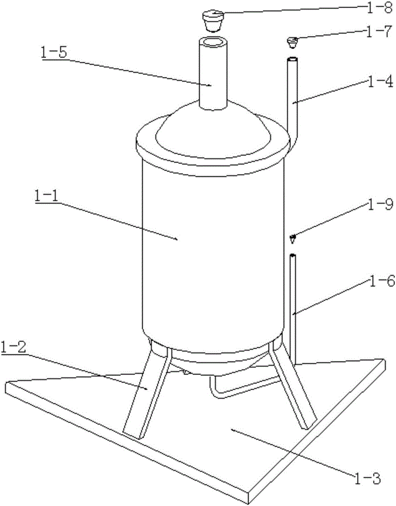
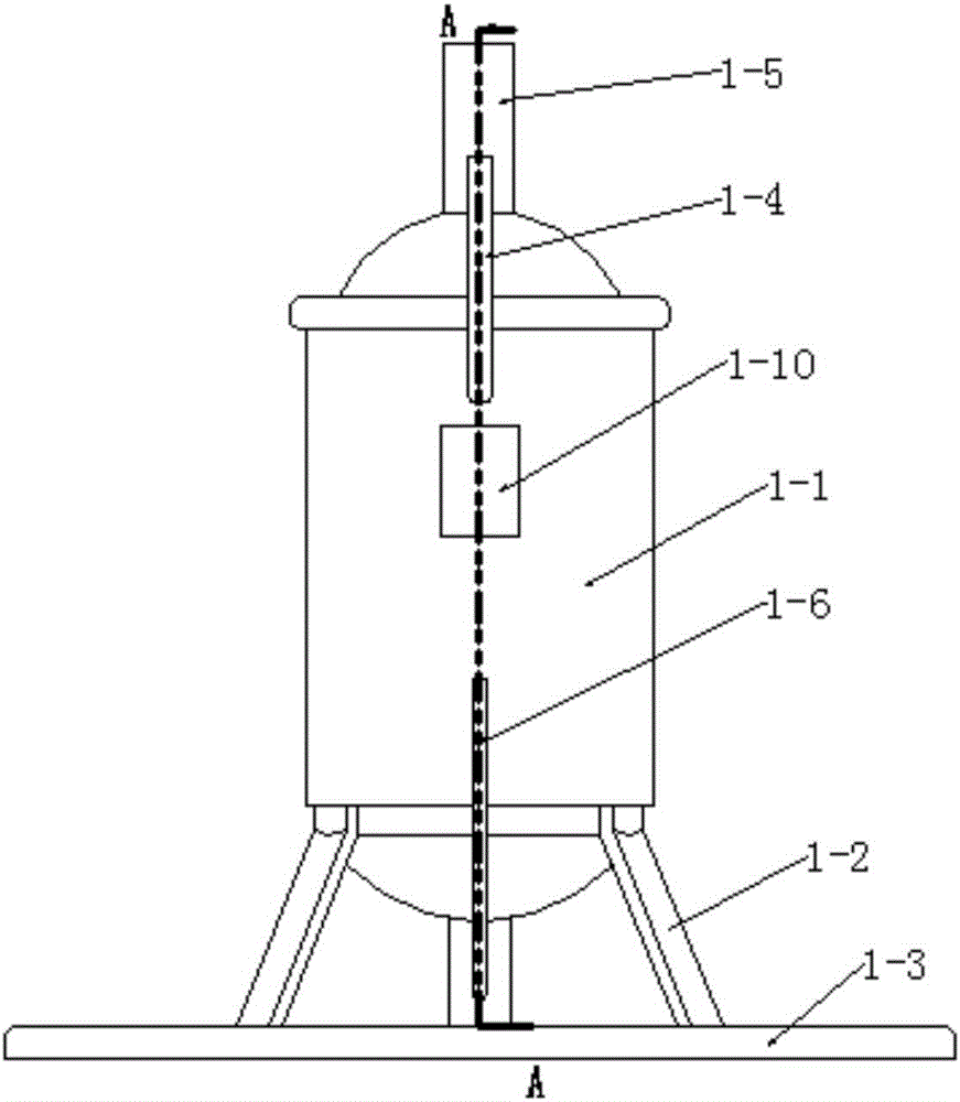
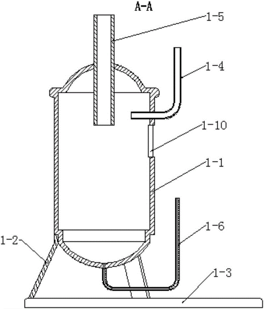
[0026] First, for the inertial oil separator, before we install it, first remove the air inlet sealing plug 1-7 at the air inlet of the air inlet pipe 1-4 and the air outlet at the outlet pipe 1-5. The air outlet sealing plug 1-8 is provided, and the oil return sealing plug 1-9 is provided at the oil outlet of the oil return pipe 1 1-6 to prevent moisture from entering the inertial oil separator and causing parts production. Rust can also prevent foreign matter from entering the inside of the inertial oil separator. Appropriate measures should be taken during the removal operation to prevent damage to the intake pipe 1-1-4, the outlet pipe 1-1-5 and the oil return pipe 1-1-6. The assembly and use of the three procedures, after the inertial oil separator is installed between the compressor discharge port and the condenser, the high-pressure refrigerant vapor with lubricating oil vapor and lubricating oil droplet particles is discharged from the intake pipe 1-1-...

Example Embodiment

[0027] Example 2:

[0028] The first choice for the filter oil separator, before we install it, remove the air inlet sealing plug 2 2-10 at the air inlet of the air inlet pipe 2 2-3 and the air outlet of the air outlet pipe 2 2-4. Equipped with air outlet sealing plug two 2-11, the first oil return pipe two 2-5 and the second oil return pipe two 2-6 are equipped with oil return sealing plug two 2-12 at the oil outlet to prevent moisture from entering The inside of the filter oil separator causes the parts to rust, and at the same time, it can prevent foreign matter from entering the inside of the filter oil separator. Appropriate measures should be taken in the removal operation to prevent damage to the intake pipe 2 2-3, the outlet pipe 2 2-4, and the second The first oil return pipe two 2-5 and the second oil return pipe two 2-6 cause damage, which affects the assembly and use of the next process. After installing the filter oil separator between the compressor exhaust port and...


PUM


Abstract

The invention discloses a novel oil separator which comprises an inertial oil separator body and a filtering oil separator body, wherein the inertial oil separator body comprises a cylinder I, supporting legs I, a baseplate, a gas inlet pipe I, a gas outlet pipe I and an oil return pipe I; the filtering oil separator body comprises a cylinder II, supporting legs II, a gas inlet pipe II, a gas outlet pipe II, a first oil return pipe II and a second oil return pipe II; the baseplate is of a triangular structure; an observation window I is arranged on the side wall of the cylinder I; an observation window II is arranged on the side wall of the cylinder II; a metal wire filtering screen is arranged at the inner top end of the cylinder II, takes the shape of a hemispherical curved surface, and is fixedly connected with the inner wall of the cylinder II; a gap is reserved between the metal wire filtering screen and the inner wall of the cylinder II; a gas outlet pipe shield is arranged at the lower end of the metal wire filtering screen; an end part of the gas outlet pipe II is positioned at the middle of the gas outlet pipe shield; and an oil collecting tank is arranged on the inner wall of the lower part inside the cylinder II. The novel oil separator disclosed by the invention is used for separating out lubricating oil in high-pressure gas and solving the problems that the heat transfer effect is impacted and the refrigerating efficiency is reduced because excessive lubricating oil enters a condenser and an evaporator.

Description

Technical field [0001] The invention belongs to the technical field of oil separation equipment. Specifically, the invention relates to a new type of oil separator. Background technique [0002] In the vapor compression refrigeration system, the compressed ammonia vapor (or freon vapor) is in a high-pressure and high-temperature superheated state. Due to the fast flow rate and high temperature of the gas discharged by the compressor, part of the lubricating oil on the cylinder wall will inevitably become oil vapor and oil droplet particles discharged together with the refrigerant vapor due to the effect of high temperature. Moreover, the higher the exhaust temperature and the faster the flow rate, the more lubricating oil will be discharged. Because the refrigerant and lubricating oil do not want to dissolve, when the lubricating oil enters the condenser and evaporator together with the refrigerant, it will be on the heat transfer wall. It condenses into a layer of oil film, whi...

Claims


Application Information

Patent Timeline
IPC IPC(8): F25B43/02
CPCF25B43/02F25B2500/16
Inventor 郭晓明
Owner WUHU SANHUA REFRIGERATION FITTINGS
Why Eureka
Try Eureka