Micro-cultivator

A micro-tiller and throttle technology, which is applied in the field of micro-tillers, can solve the problems that the adjustment handle is not well positioned, the limit is not obtained, and the controllability of the micro-tiller is poor, and the connection is simple and reliable. , Low manufacturing cost, and improved maneuverability

Inactive Publication Date: 2011-05-25
周树明 +1
View PDF7 Cites 1 Cited by
  • Summary
  • Abstract
  • Description
  • Claims
  • Application Information

AI Technical Summary

Problems solved by technology

At present, most micro tillage machines realize walking and parking by installing a throttle control device on the micro tiller. This kind of throttle control device mainly includes a mounting seat, a positioning plate is arranged on the mounting seat, and a limit position is set above the positioning plate. The mounting seat, the positioning plate and the limiting plate are fixed through the same adjusting bolt, and an adjusting handle is installed between the positioning plate and the limiting plate, and the adjusting handle is covered on the adjusting bolt, and the The adjusting handle can be rotated around the adjusti

Method used


Image

  • Micro-cultivator
  • Micro-cultivator
  • Micro-cultivator

Examples


Example Embodiment

[0024] Below in conjunction with accompanying drawing and embodiment, the present invention will be further described:
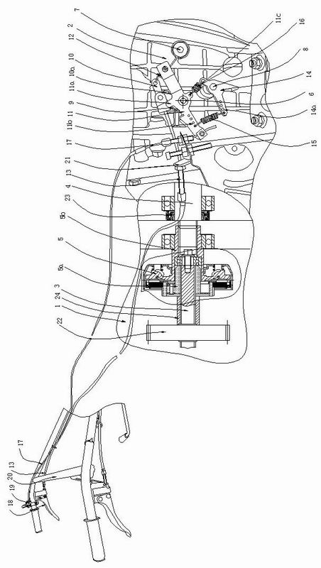
[0025] like Figure 1 to Figure 4 The micro-cultivator shown is composed of a reduction box 1, a crankcase 2, a handrail frame 20 and other components, and the reduction box 1, the crankcase 2, the handrail frame 20 and other components are all in the prior art, and here Without further elaboration, the reduction box body 1 is fixed on the left side of the crankcase body 2, the output shaft 3 is installed in the reduction box body 1, the crankshaft 4 is installed in the crankcase body 2, and the crankshaft 4. The left end extends into the reduction box body 1, and an oil seal 23 is sleeved on the crankshaft 4. The output shaft 3 and the crankshaft 4 are arranged opposite to each other, and a driving gear 22 is fixedly sleeved at the left end of the output shaft 3. A clutch 5 is installed between the output shaft 3 and the crankshaft 4, the driven shaft sleeve...


PUM


Abstract

The invention discloses a micro-cultivator. A clutch capable of automatically clutching is installed between an output shaft and a crank shaft; a crank shaft box body is provided with an operating arm mounting post and a spring mounting post provided with a return support, wherein the operating arm mounting post is successively sheathed with an accelerator return torsional spring, the return support and an accelerator operating arm from inside to outside; the accelerator is provided with an accelerator arm; a return stay wire spring is connected between the right end of the return support andthe spring mounting post; the left end of the return support is connected with an accelerator return stay wire connected with a shutdown handle; the middle of the accelerator operating arm is installed on the accelerator arm mounting post; the middle of the accelerator arm is installed on the accelerator; a refuelling spring and an fuel return spring which are respectively positioned on the left side and the right side of the accelerator are connected between the accelerator operating arm and the accelerator arm; an accelerator wire is connected between the accelerator operating arm and a control device; and the return support and the accelerator operating arm are respectively and correspondingly provided with a pushing support lug and a stirring support lug. The micro-cultivator can better automatically clutch, accelerate, idle and stop.

Description

technical field [0001] The invention relates to an agricultural machine, in particular to a tiller. Background technique [0002] The clutch is an important part located on the engine, and its function is to transmit or cut off the power of the engine. At present, there are mainly manual clutches in agricultural machines, and there are also a small number of automatic clutches, such as shoe clutches. When the shoe clutch used on the agricultural machine transmits and cuts off the power, there is no buffer mechanism to buffer the moment of power output and cut-off, which is basically equivalent to a hard connection to output power so that the entire clutch assembly is working. At this time, the damage between the transmission and connection parts is relatively large, and it is easy to deform. At the same time, the noise is relatively large when the clutch is switching power during operation. Existing manual clutches have a buffer structure, such as a wet traditional frictio...

Claims


Application Information

Patent Timeline
IPC IPC(8): F02D33/00F02B61/06F02F7/00
Inventor 周树明张坤
Owner 周树明
Why Eureka
Try Eureka