
A Graph Generation Method for System Failure Based on Time Series Relationship

A technology of time sequence relationship and relationship, which is applied in the direction of ammunition testing, offensive equipment, instruments, etc., can solve problems such as state space explosion, and achieve the effect of solving state space explosion

Active Publication Date: 2018-07-27
NANJING UNIV OF AERONAUTICS & ASTRONAUTICS
View PDF9 Cites 0 Cited by
  • Summary
  • Abstract
  • Description
  • Claims
  • Application Information

AI Technical Summary

Problems solved by technology

[0004] The technical problem to be solved by the present invention is to provide a system failure generation diagram method based on time series relationship, which effectively solves the state space explosion problem existing in the generation process of the system failure generation diagram

Method used


Image

  • A Graph Generation Method for System Failure Based on Time Series Relationship
  • A Graph Generation Method for System Failure Based on Time Series Relationship
  • A Graph Generation Method for System Failure Based on Time Series Relationship

Examples


Embodiment Construction

[0036] Embodiments of the invention are described in detail below, examples of which are illustrated in the accompanying drawings. The embodiments described below by referring to the figures are exemplary only for explaining the present invention and should not be construed as limiting the present invention.

[0037] In order to directly convert the state-event fault tree into a system failure generation diagram, the state-event fault tree must satisfy the following prerequisites:

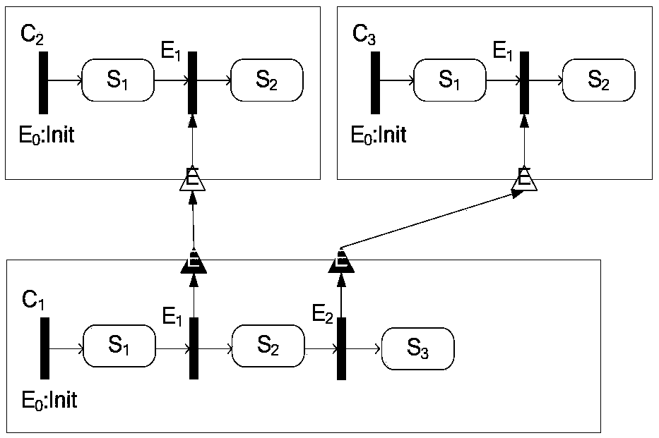
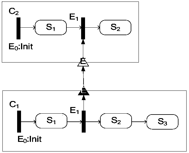
[0038](1) The dynamic part of the state event fault tree only allows event port interaction. The dynamic part of a state-event fault tree consists of component internal state machines and state dependencies. Only trigger events are allowed to shape dependencies between state machines;

[0039] (2) The causal failure relationship model can only pass through pure state gates. This rule makes the logic gate semantics of the state event fault tree consistent with the logic gate of the standard fault...


PUM


Abstract

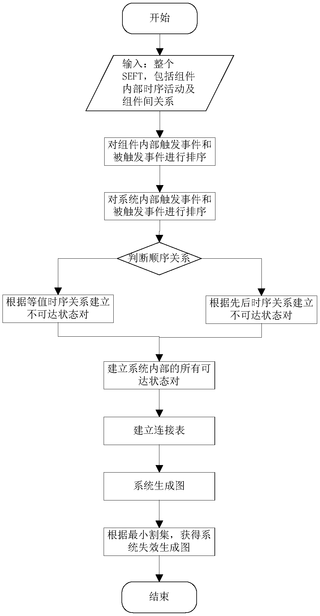
The invention discloses a system failure spanning graph method based on sequential relationship. The method comprises the steps: first, sequencing components by recognizing the sequential behavior of triggering or triggered type events in the components in a system, and thus obtaining the states which cannot be reached at the same time among the inner components of the system; then, excluding unreachable state pairs, setting a cartesian product for the states which can be reached at the same time among the components, and thus obtaining all reachable state pairs of the system; finally, obtaining a system failure spanning graph according to a connection table and a minimum cutest. The system failure spanning graph method based on the sequential relationship effectively solves the problem of state space explosion existing in the spanning process of the system failure spanning graph and provides a new method for the reachable graph of a state event fault tree generation system.

Description

technical field [0001] The invention relates to a method for generating diagrams of system failures based on timing relationships, in particular to a method for generating diagrams for system failures based on timing relationships inside state event fault tree components. Background technique [0002] Because the combat system has some special properties, such as timing relationship, functional dependence, etc., it is difficult to apply the common fault tree to the combat system. The state event fault tree can not only express the internal timing behavior activities of the components, but also express the causal failure relationship of the system, which is suitable for describing the failure causal chain of the combat system. Due to the lack of strict semantics of the state event fault tree, most of the analysis process is based on model conversion, which is converted to DSPN model or Markov model, but there is a problem of state space explosion in the equivalent conversion ...

Claims


Application Information

Patent Timeline
Patent Type & Authority Patents(China)
IPC IPC(8): F42B35/00G06F17/50
CPCF42B35/00G06F30/20
Inventor 燕雪峰范亚琼
Owner NANJING UNIV OF AERONAUTICS & ASTRONAUTICS
Learn More