Mine emergency stop locking button device
A button, mining technology, applied in the field of mine emergency stop locking button device, can solve the problems of difficult to observe the indicator light, insufficient insulation and sealing, unreliable sealing structure of the lock, etc., and achieves obvious warning effect. , Beautify the appearance, prevent the effect of winding
- Summary
- Abstract
- Description
- Claims
- Application Information
AI Technical Summary
Problems solved by technology
Method used
Image

Examples
Embodiment 1
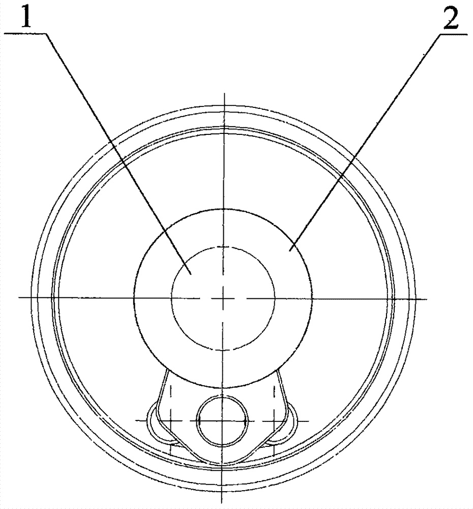
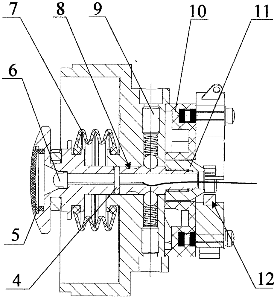
[0026] see image 3 and Figure 4 , the working principle of the present invention is as follows: a mine emergency stop locking button device, including locking button 2, locking plate 3, locking bar 16, switch mounting seat 10, pin 13 and micro switch 19, the through hole of locking button 2 A light-emitting diode 6 is fixedly installed inside, and a wire 18 is connected to the rear end of the light-emitting diode; a lampshade sealing ring 5 is installed in the groove at the front end of the lock button 2; the lampshade 1 is installed in the lock button 2 through snap fit;
[0027] The locking bar 16 is fastened on the locking seat 14, and the locking button 2 bar part is fitted in the groove of the locking seat 14 by an external clearance; the locking bar 16 passes through the round hole at the lower end of the locking plate 3 and is connected with the locking plate 3; the button cap 11 Installed on the top of the locking button 2; a top screw 9 is installed at the vertical...
Embodiment 2
[0032] see Figure 1 to Figure 5 , the working principle of the present invention is as follows: a mine emergency stop locking button device, including locking button 2, locking plate 3, locking bar 16, switch mounting seat 10, pin 13 and micro switch 19, the through hole of locking button 2 A light-emitting diode 6 is fixedly installed inside, and a wire 18 is connected to the rear end of the light-emitting diode; a lampshade sealing ring 5 is installed in the groove at the front end of the lock button 2; the lampshade 1 is installed in the lock button 2 through snap fit;
[0033] The locking bar 16 is fastened on the locking seat 14, and the locking button 2 bar part is fitted in the groove of the locking seat 14 by an external clearance; the locking bar 16 passes through the round hole at the lower end of the locking plate 3 and is connected with the locking plate 3; the button cap 11 Installed on the top of the locking button 2; a top screw 9 is installed at the vertical p...
Embodiment 3
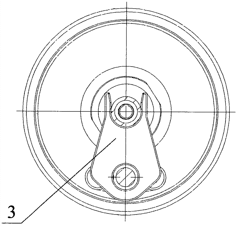
[0038] refer to Figure 4 , Different from Embodiment 1 and Embodiment 2, the number of micro switches in the present invention is three.
[0039] The button cap is a tapered structure, and the button cap 11 of the tapered structure is threaded and installed on the thread at the top of the locking button 2. The number of limiting grooves is 2, and a cylindrical compression spring is coaxially installed on the front end of the top screw. Equipped with a ball. The locking button is respectively shaped on the front and rear two limiting grooves 8 at the position of the steel ball, and the two limiting grooves can be respectively limited by the steel ball when the locking button is axially displaced. The number of top wires is also 2. There is a groove on the button cap, and the bottom of the pin 13 is inserted into the groove of the button cap, and the pin 13 is installed in the eccentric cavity of the switch mounting seat 10 with clearance fit and fastened with screws to form ...
PUM
 Abstract
Description
Claims
Application Information
 - R&D Engineer
- R&D Manager
- IP Professional
- Industry Leading Data Capabilities
- Powerful AI technology
- Patent DNA Extraction
Browse by: Latest US Patents, China's latest patents, Technical Efficacy Thesaurus, Application Domain, Technology Topic.
© 2024 PatSnap. All rights reserved.Legal|Privacy policy|Modern Slavery Act Transparency Statement|Sitemap