
Antenna devices and electronic equipment

An antenna device and antenna technology, which can be applied in directions such as antenna arrays and radiating element structures that are individually energized, and can solve problems such as the inability to realize omnidirectional signal switching of directional signals.

Active Publication Date: 2019-09-20
QINGDAO HISENSE MOBILE COMM TECH CO LTD
View PDF7 Cites 0 Cited by
  • Summary
  • Abstract
  • Description
  • Claims
  • Application Information

AI Technical Summary

Problems solved by technology

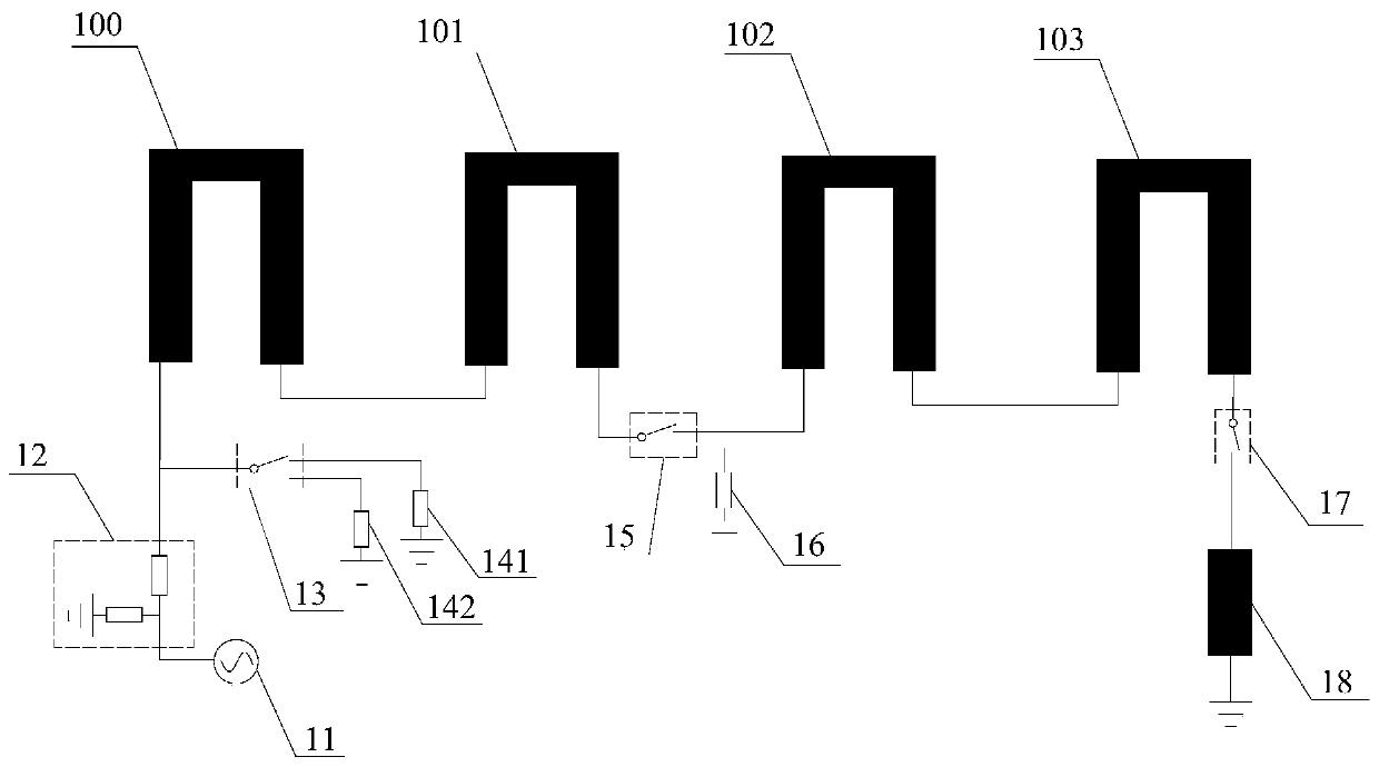
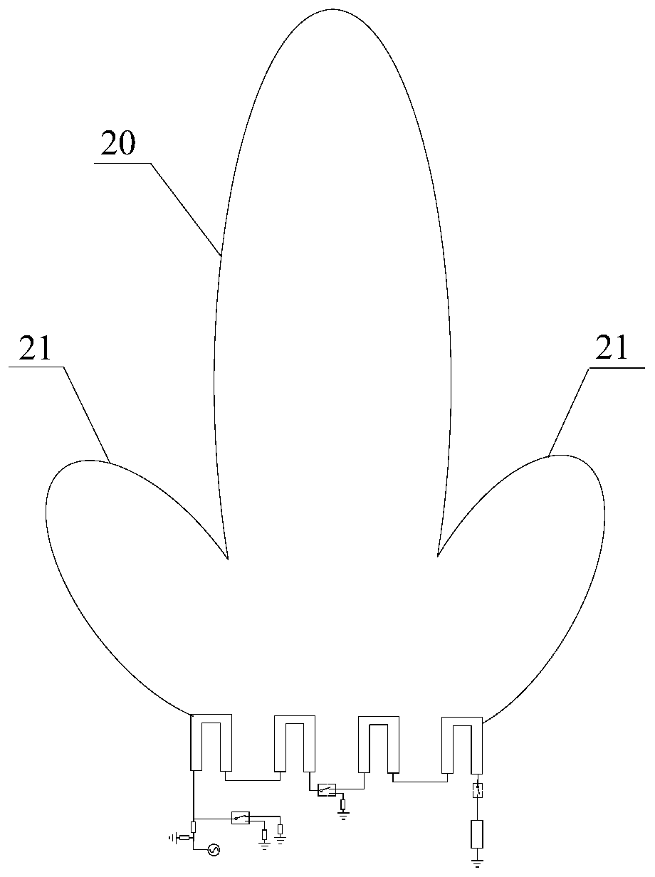
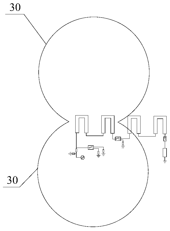
[0005] The purpose of the present disclosure is to provide an antenna device and electronic equipment including the antenna device, which solves the problem that the same antenna cannot switch between directional signal transmission and reception and omnidirectional signal transmission and reception, so that the same antenna can be applied in different scenarios

Method used


Image

  • Antenna devices and electronic equipment
  • Antenna devices and electronic equipment
  • Antenna devices and electronic equipment

Examples


Embodiment Construction

[0018] Example embodiments will now be described more fully with reference to the accompanying drawings. Example embodiments may, however, be embodied in many forms and should not be construed as limited to the examples set forth herein; rather, these embodiments are provided so that this disclosure will be thorough and complete and will fully convey the concept of example embodiments to those skilled in the art. The described features, structures, or characteristics may be combined in any suitable manner in one or more embodiments. In the following description, numerous specific details are provided in order to give a thorough understanding of embodiments of the present disclosure. However, those skilled in the art will appreciate that the technical solutions of the present disclosure may be practiced without one or more of the specific details being omitted, or other methods, components, devices, steps, etc. may be adopted. In other instances, well-known technical solution...


PUM


Abstract

The present invention relates to an antenna device and electronic equipment. The antenna device comprises a plurality of antenna units and a switch unit. The plurality of antenna units are arranged in an array manner. The plurality of antenna unit comprises a first antenna unit and second antenna unit adjacent to the first antenna unit. The first antenna unit receives a signal sent by a signal source before the signal reception of the second antenna unit. One end of the switch unit is connected with the first antenna unit, and the other end of the switch unit is connected with the second antenna unit or a pair of matched devices. The invention realizes the switching between a directional antenna and an omni-directional antenna. Meanwhile, the problem in the prior art that an antenna cannot be compatible with different application scenarios can be solved. Therefore, the requirements of different application scenarios can be met.

Description

technical field [0001] The present disclosure relates to the technical field of electronic equipment, and in particular, to an antenna device and electronic equipment including the antenna device. Background technique [0002] With the development of electronic equipment and Internet technology, wireless communication technology has become the main way for people to communicate. As one of the important components necessary for wireless communication equipment, the antenna is mainly used to convert electrical signals into electromagnetic waves, transmit and receive electromagnetic waves, and convert the received electromagnetic waves into electrical signals. In addition, the application of antennas is not limited to large-scale communication devices and mobile communication terminals (eg, mobile phones, tablets, etc.), and is also widely used in smart home appliances and wearable devices. [0003] At present, antennas designed using traditional antenna design methods can onl...

Claims


Application Information

Patent Timeline
Patent Type & Authority Patents(China)
IPC IPC(8): H01Q1/36H01Q21/08
Inventor 胡育根耿建辉韩方
Owner QINGDAO HISENSE MOBILE COMM TECH CO LTD
Learn More