Method and device for indicating transmission mode

A technology of transmission mode and indication, applied in the field of communication, can solve the problem of inability to perform dynamic switching, and achieve the effect of switching

Active Publication Date: 2010-04-07
ZTE CORP
View PDF3 Cites 26 Cited by
  • Summary
  • Abstract
  • Description
  • Claims
  • Application Information

AI Technical Summary

Problems solved by technology

[0004] The present invention is proposed in view of the problem that single-user transmission and multi-user transmission cannot be dynamically switched in the relat

Method used


Image

  • Method and device for indicating transmission mode
  • Method and device for indicating transmission mode
  • Method and device for indicating transmission mode

Examples


example 1

[0044] In this example, in the scenario of multi-antenna input and output (MIMO), the newly defined DCI Format X can be used to indicate single-user or multi-user transmission. The 4 bits in this DCI format can be defined as follows:

[0045]

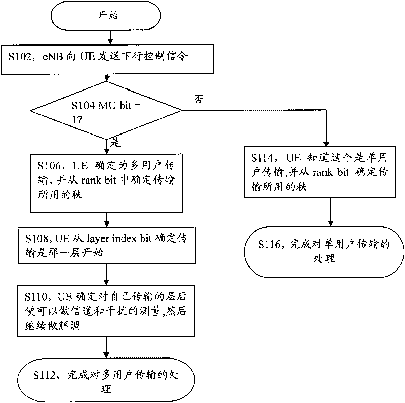
[0046] In single-user transmission mode, the MU bit indicator is 0, which means that this is a single-user transmission. The eNB should notify the UE of the rank used for transmission to the UE. 3 bits can be used to represent the rank, that is, in single-user transmission The maximum rank used in is 8.

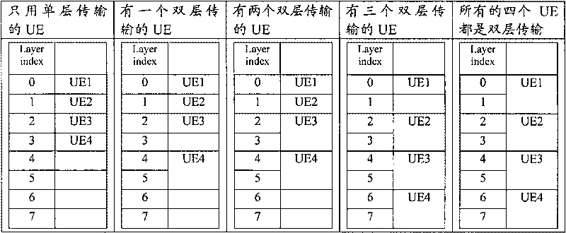
[0047] In the multi-user transmission mode, the MU bit is indicated as 1, indicating that this is a multi-user transmission. The eNB shall inform the UE of the rank used for transmission to the UE and which layer to start transmitting to the UE. 1 bit can be used to represent Rank, that is, the maximum rank used in multi-user transmission is 2, and 2 bits (Layer Index bit) can be used to inform the UE which layer starts to transmit to the U...


PUM


Abstract

The invention discloses a method and a device for indicating a transmission mode. The method comprises that: a transmitting end sets indicative information in a downlink control information format, wherein the indicative information is used for indicating a receiving end that the transmission mode adopted by the transmitting end is a single-user transmission mode or a multi-user transmission mode. The method and the device for indicating the transmission mode in the invention realize switching between single-user multi-layer transmission and multi-user transmission.

Description

Technical field [0001] The present invention relates to the field of communications, and in particular to a method and device for indicating a transmission mode. Background technique [0002] In wireless communication, if multiple antennas are used at the transmitting end (for example, base station, referred to as eNB), spatial multiplexing can be adopted to increase the transmission rate, that is, different antenna positions on the same time-frequency resource at the transmitting end To transmit different data, multiple antennas are also used at the receiving end (for example, user equipment, referred to as UE). In the case of a single user, all antenna resources can be allocated to the same user. This transmission form is called single user multiple input Multiple output (Single User-Multiple Input Multiple Output, referred to as SU-MIMO). In addition, the resources of different antenna spaces can also be allocated to different users in the case of multiple users. This transmis...

Claims


Application Information

Patent Timeline
IPC IPC(8): H04W28/06H04W48/12H04L1/00
CPCH04W72/005H04W72/30
Inventor 李儒岳郁光辉
Owner ZTE CORP
Why Eureka
Try Eureka