Beam part drawing mold

A technology for drawing dies and drawbeads, which is applied in the direction of forming tools, manufacturing tools, metal processing equipment, etc., can solve the problems of wrinkling at both ends, reduce the possibility of wrinkling, achieve good positioning effect, and improve The effect of material utilization and molding effect

Active Publication Date: 2017-07-14
ANHUI JIANGHUAI AUTOMOBILE GRP CORP LTD
View PDF8 Cites 4 Cited by
  • Summary
  • Abstract
  • Description
  • Claims
  • Application Information

AI Technical Summary

Problems solved by technology

[0003] The purpose of the present invention is to provide a beam drawing die to solve the problem of wrinkling at both ends in the prior art

Method used


Image

  • Beam part drawing mold
  • Beam part drawing mold
  • Beam part drawing mold

Examples


Embodiment Construction

[0033] In order to enable those skilled in the art to better understand the technical solution of the present invention, the solution will be further described in detail below in conjunction with specific embodiments.

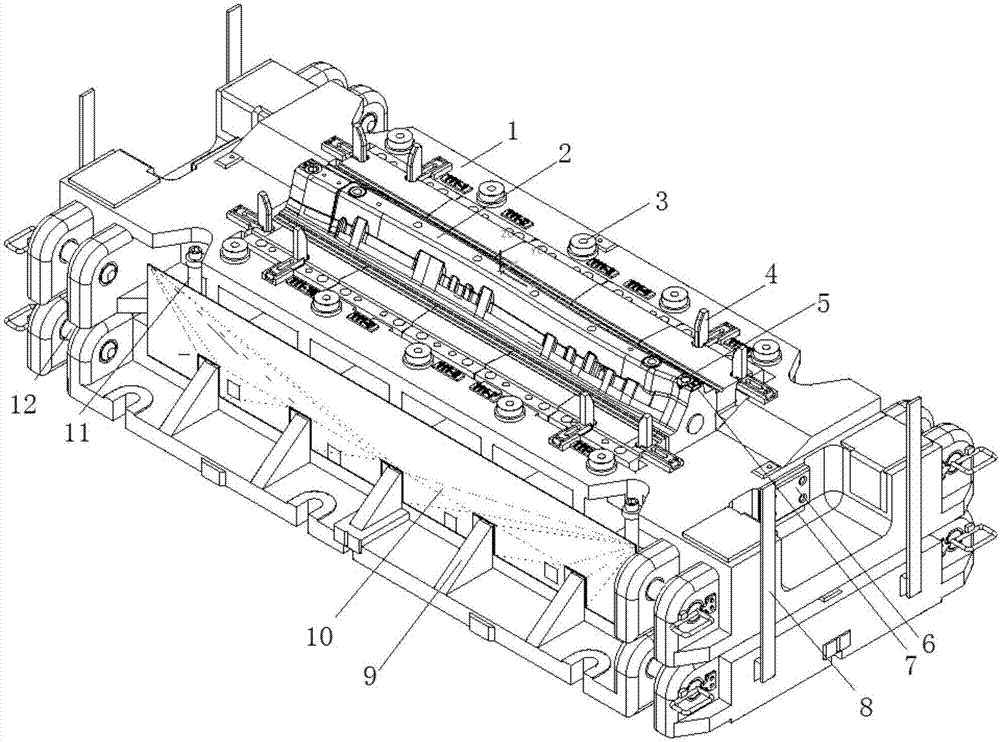
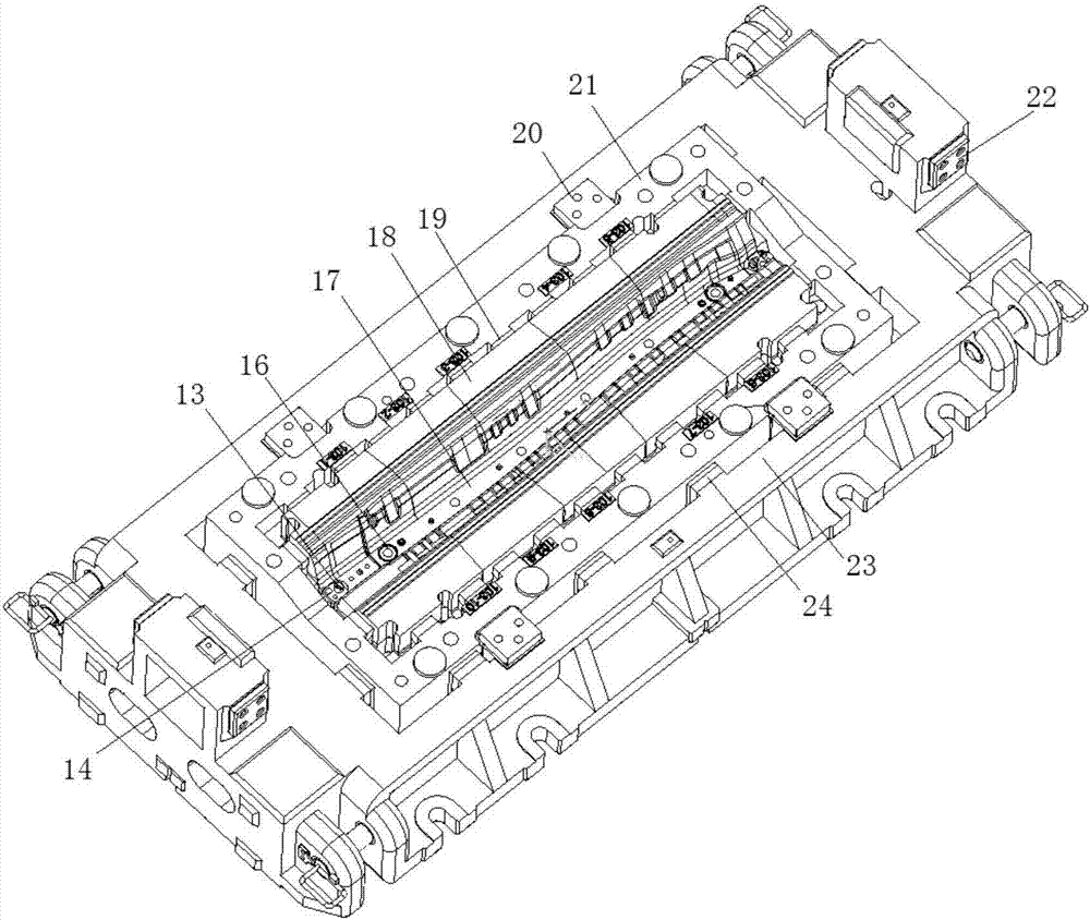
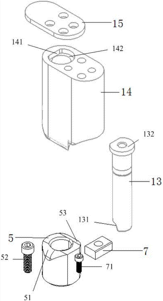
[0034] Such as Figure 1 to Figure 4 As shown, the embodiment of the present invention provides a beam drawing die, which includes an upper die base 23, a lower die base 9, and a split die 21 arranged on the upper die base 23, and a lower die base 9. The split punch 2 on the seat 9, two flanging punches 13, and two flanging dies 5, wherein, the two sides of the split die 21 are oppositely provided with two drawbeads 29, and the drawbeads 29 The direction of extension is the same as that of the split die 21; the two flanging punches 13 are respectively arranged at the two ends of the split die 21, and the two flanging dies 5 are respectively arranged at the two ends of the split die 2, The two flanging dies 5 are matched with the two flanging punches 13 in one-...


PUM


Abstract

The invention provides a beam part drawing mold. The beam part drawing mold comprises an upper mold base, a lower mold base, a split concave mold arranged on the upper mold base, a split convex mold arranged on the lower mold base, two flanged convex molds and two flanged concave molds; two drawing ribs are oppositely arranged on two sides of the split concave mold; the extending direction of the drawing ribs is the same with the extending direction of the split concave mold; the two flanged convex molds are respectively arranged at two ends of the split concave mold; the two flanged concave molds are respectively arranged at two ends of the split convex mold; the two flanged concave molds are correspondingly matched with the two flanged convex molds one to one; flanged molding surfaces are arranged at one ends, far from the split concave mold, of the flanged convex molds; and matching surfaces matched with the flanged molding surfaces are arranged at one ends, far from the split convex mold, of the flanged concave molds. The beam part drawing mold can greatly reduce the corrugation possibility of two ends, is better in subsequent positioning effect, and meanwhile, can improve the material utilization rate and the forming effect.

Description

technical field [0001] The invention relates to the technical field of die structures, in particular to a drawing die for beams. Background technique [0002] At present, automotive stamping parts are mainly formed by cold stamping, and the forming process mainly includes drawing, trimming, punching, flanging and shaping, etc., and the drawing process of stamping parts will directly affect the forming effect of the part and the final quality of the product. In the drawing die surface of the existing beam parts, the process supplementary surface of the forming die surface is provided with a peripheral drawing bead or an open drawing. When the former is drawn and formed, the die and the blank holder cooperate to compress the blank circumference. Then the punch is formed. During the forming process, the drawbead locks the surrounding blank to control the flow speed of the blank. However, since a certain distance needs to be left between the drawbead and the edge of the product...

Claims


Application Information

Patent Timeline
Patent Type & Authority Applications(China)
IPC IPC(8): B21D37/10
CPCB21D37/10
Inventor 何鹏申李伟浩王肖英吕晓如高双明赵鸿鹄
Owner ANHUI JIANGHUAI AUTOMOBILE GRP CORP LTD
Why Eureka
Try Eureka