Display module and terminal

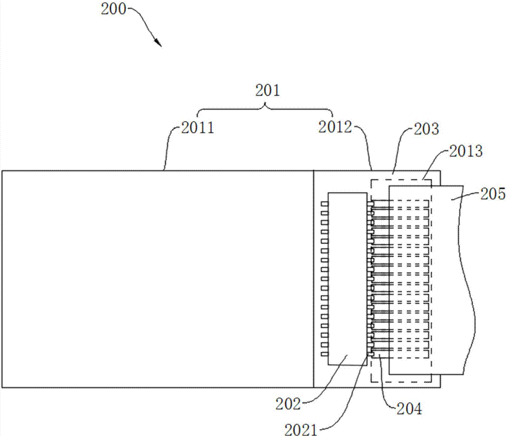
A display module and pad group technology, applied in optics, instruments, electrical components, etc., can solve the problems of increasing the area and proportion of the display panel 201, the screen-to-body ratio difference of the display module 200, and the binding area occupying a large area, etc. , to achieve the effect of narrow bezel design, large screen ratio, and reduced width

Inactive Publication Date: 2017-07-14
WUHAN CHINA STAR OPTOELECTRONICS TECH CO LTD
View PDF7 Cites 32 Cited by
  • Summary
  • Abstract
  • Description
  • Claims
  • Application Information

AI Technical Summary

Problems solved by technology

In order to ensure that the circuit board 205 is in good contact with the pad group 204, it is necessary to ensure that the length of the pads of the pad group 204 is sufficient, which will cause the bonding area 2013 to occupy a larger area, increasing the area and proportion of the frame area 2012 of the display panel 201, Make the screen ratio of the display module 200 poor

Method used


Image

  • Display module and terminal
  • Display module and terminal
  • Display module and terminal

Examples


Embodiment Construction

[0035] The technical solutions in the embodiments of the present invention will be described below with reference to the accompanying drawings in the embodiments of the present invention. Obviously, the described embodiments are only some of the embodiments of the present invention, not all of them. Based on the embodiments of the present invention, all other embodiments obtained by persons of ordinary skill in the art without creative efforts fall within the protection scope of the present invention.

[0036] In addition, the following descriptions of the various embodiments refer to the attached drawings to illustrate specific embodiments in which the present invention can be implemented. The directional terms mentioned in the present invention, for example, "upper", "lower", "front", "rear", "left", "right", "inner", "outer", "side", etc., only is to refer to the direction of the attached drawings. Therefore, the direction terms used are for better and more clearly explaini...


PUM


Abstract

The invention discloses a display module comprising an array substrate, a driving chip, a bonding pad set and a flexible circuit board. The array substrate a top face and a bottom face which are oppositely arranged, and a via hole penetrating through the top face and the bottom face, and the via hole is filled with a conductive material in order to form a conductive portion. The driving chip is arranged on the top face, and a part of pins of the driving chip are electrically connected to the conductive portion. The bonding pad set is arranged on the bottom face and right faces the driving chip, and the bonding pad set is electrically connected to the conductive portion. The flexible circuit board is bound to the bonding pad set. The screen-to-body ratio of the display module is relatively large. The invention also discloses a terminal.

Description

technical field [0001] The present invention relates to the field of display technology, in particular to a display module and a terminal using the display module. Background technique [0002] Such as figure 1 As shown, the conventional display module 200 generally includes a display panel 201 , a driver IC (Driver IC) 202 and a circuit board 205 , and the circuit board 205 is a transmission medium for carrying analog and digital signals. The way that the display module 200 currently applied to the terminal transmits the signal to the driver chip 202 on the display panel 201 is as follows: the display panel 201 includes a display area 2011 and a frame area 2012 arranged on one side of the display area 2011, and the driver chip 202 is arranged on In the frame area 2012 and fixed on the front surface of the array substrate 203, part of the pins 2021 of the driver chip 202 are electrically connected to the signal wiring in the display area 2011, and the pad group 204 is arran...

Claims


Application Information

Patent Timeline
Patent Type & Authority Applications(China)
IPC IPC(8): G02F1/1345H01L27/32
CPCG02F1/13452H10K59/12G02F2201/42G02F1/13458G02F1/13454G02F1/133305
Inventor 曹洪睿秦杰辉
Owner WUHAN CHINA STAR OPTOELECTRONICS TECH CO LTD
Why Eureka
Try Eureka