Self-controlled plug-in new energy vehicle charging pile device

A technology for new energy vehicles and charging piles, which is applied in electric vehicle charging technology, devices for preventing contact with live contacts, and parts for connecting devices, etc. The effect of stable plug-in operation and prevention of electric shock accidents

Active Publication Date: 2017-07-18
新乡市合众鑫辉车业有限公司
View PDF5 Cites 21 Cited by
  • Summary
  • Abstract
  • Description
  • Claims
  • Application Information

AI Technical Summary

Problems solved by technology

Electric vehicles are inseparable from charging piles, but in the process of charging electric vehicles with existing charging piles, they are all manually plugged and unplugged by personnel. During the plugging and unplugging process, the charging plug is prone to arc due to the influence of voltage, and the generation of arc is easy to cause The electric shock of the user has a certain potential danger to the user, which will cause safety accidents and cause casualties, and the force of the personnel on the plug is unstable, which may easily lead to equipment damage, and is time-consuming and labor-intensive.

Method used


Image

  • Self-controlled plug-in new energy vehicle charging pile device
  • Self-controlled plug-in new energy vehicle charging pile device
  • Self-controlled plug-in new energy vehicle charging pile device

Examples


Embodiment Construction

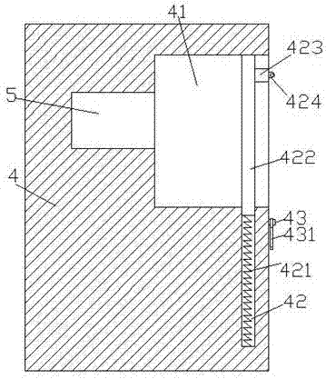
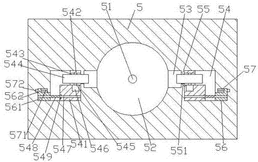
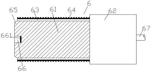
[0019] Such as Figure 1-Figure 4 As shown, a new energy vehicle charging pile device with self-control plugging according to the present invention includes a pile body 4 and a charging gun head 6, a storage groove 41 is provided in the pile body 4, and a storage groove 41 is arranged in the inner end surface of the storage groove 41. There is a charging and connecting mechanism 5, and the charging and connecting mechanism 5 is provided with a socket hole 52, and a power supply pin 51 is provided at the middle position of the inner end surface of the socket hole 52, and the left and right sides of the socket hole 52 are symmetrical There are guide grooves 53 extending along the insertion holes 52 , each of the guide grooves 53 is provided with a sliding cavity 54 in the charging and mounting mechanism 5 on the side away from the insertion holes 52 , and the A partition 55 is provided between the sliding chamber 54 and the guide groove 53 , and a through groove 551 is provided ...


PUM


Abstract

The invention discloses a self-controlled plug-in new energy vehicle charging pile device. The self-controlled plug-in new energy vehicle charging pile device comprises a pile body and a charging gun head. A storage groove is formed in the pile body. A charging plug-in mechanism is arranged in the inside end face of the storage groove. A plug-in hole is formed in the charging plug-in mechanism. A power supply pin is arranged on the middle position of the inside end face of the plug-in hole. Guide grooves extending along the plug-in hole are symmetrically arranged on the left side and the right side of the plug-in hole. A sliding cavity is arranged on the side, far from the plug-in hole, of each guide groove in the charging plug-in mechanism. A baffle plate is arranged between each sliding cavity and each guide groove. A through groove is formed in each baffle plate. A first sliding groove is formed in the side, far from the baffle plate, of each sliding cavity in the charging plug-in mechanism, and the first sliding grooves are located on the bottom positions of the outer sides of the sliding cavities and communicate with the sliding cavities correspondingly. A second sliding groove is formed above the outer side of each first sliding groove in the charging plug-in mechanism. A guide sliding rod is arranged between each sliding cavity and each first sliding groove. A first sliding block is connected to each guide sliding rod in each sliding cavity in a sliding and matched mode. A second sliding block is connected to each guide sliding rod in each first sliding groove in a sliding and matched mode.

Description

technical field [0001] The invention relates to the technical field of new energy vehicle charging, in particular to a new energy vehicle charging pile device with self-control plugging. Background technique [0002] With the gradual depletion of oil resources, electric vehicles have been well developed in recent years. An electric vehicle refers to a vehicle that uses an electric motor to drive the wheels. Compared with gasoline vehicles, it is more energy-saving and environmentally friendly, so it is being promoted by countries all over the world. Electric vehicles are inseparable from charging piles, but in the process of charging electric vehicles with existing charging piles, they are all manually plugged and unplugged by personnel. During the plugging and unplugging process, the charging plug is prone to arc due to the influence of voltage, and the generation of arc is easy to cause The electric shock of the user has a certain potential danger to the user, which will...

Claims


Application Information

Patent Timeline
Patent Type & Authority Applications(China)
IPC IPC(8): B60L11/18H01R13/44H01R13/631H01R43/26
CPCB60L53/31H01R13/44H01R13/631H01R43/26H01R2201/26Y02T10/70Y02T10/7072Y02T90/12
Inventor 梁敏华
Owner 新乡市合众鑫辉车业有限公司
Why Eureka
Try Eureka