Pressure reducing valve

A pressure reducing valve and valve body technology, applied in the field of pressure reducing valves, can solve the problems of low sealing performance of the lower valve cover, reduced safety and reliability, poor sealing effect, etc., and achieve low production cost, simple structure, and stable pressure regulation strong effect

Inactive Publication Date: 2017-07-18
吴廷贵
View PDF0 Cites 3 Cited by
  • Summary
  • Abstract
  • Description
  • Claims
  • Application Information

AI Technical Summary

Problems solved by technology

[0003] The present invention is aimed at the current general pressure reducing valve which is adjusted by two parts, the split wheel and the lifting screw. Under high temperature and high pressure or high temperature and ultra-high pressure conditions, most of them use double-seat pressure reducing valves. The upper bonnet of the double-seat pressure reducing valve adopts pressure self-tightening seal, and the lower bonnet adopts the ordinary flange gasket sealing form, so that the sealing performance of the lower bonnet is low, so that the pressure reducing valve can operate under high temperature and high pressure or high temperature and ultra-high pressure. Under working conditions, the sealing effect is not good, which will lead to leakage and reduce the safety and reliability of the problem. A pressure reducing valve is designed

Method used


Image

  • Pressure reducing valve

Examples


Embodiment Construction

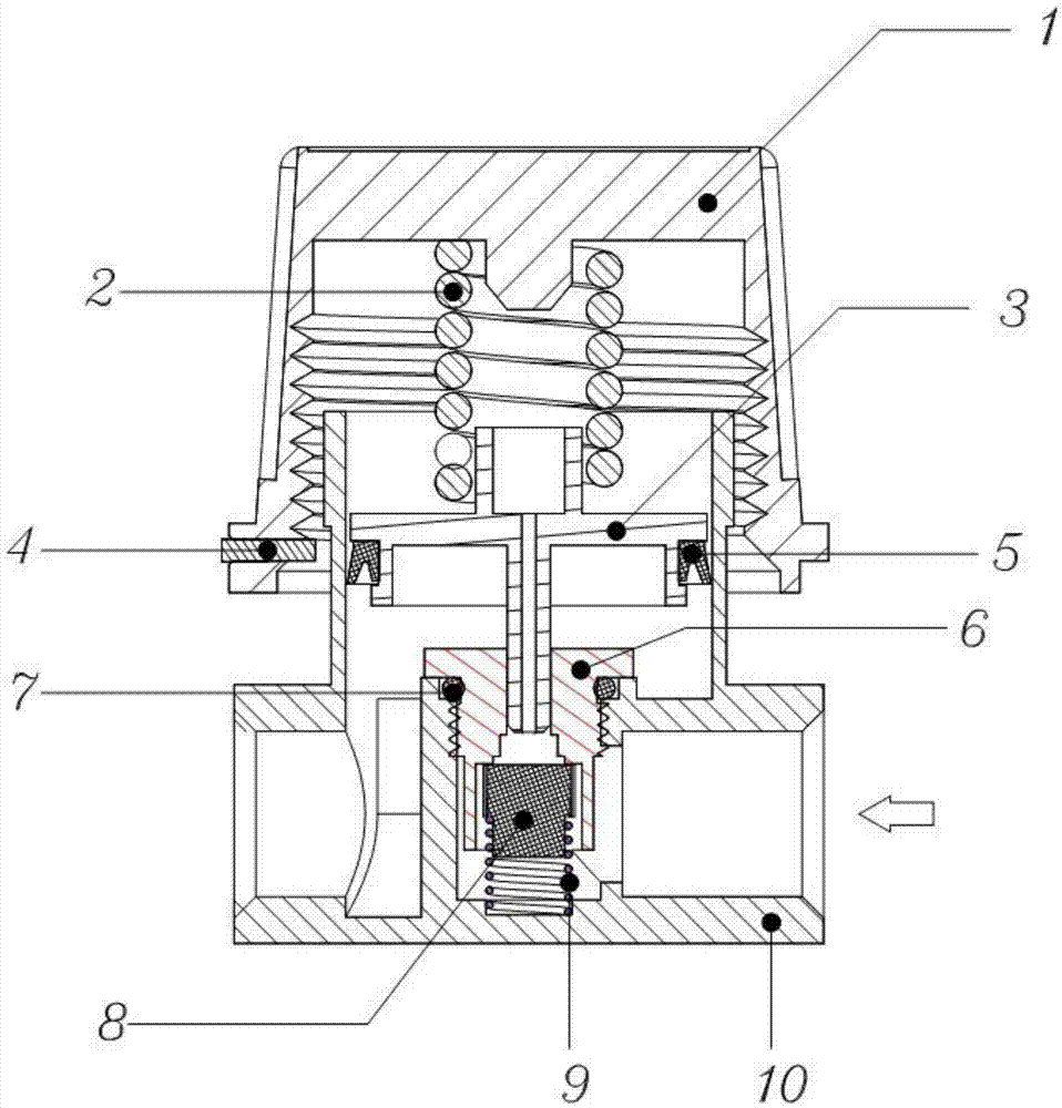
[0014] like figure 1 Shown: pressure reducing valve, its structure includes: bonnet 1, fixed value spring 2, piston 3, stop pin 4, Y-ring 5, fixed seat 6, O-ring 7, spring plunger 8, balance spring 9, Valve body 10; a valve body 10 with an inner cavity, a bonnet 1 sleeved on the outside of the valve body 10, fixedly connected with the valve body 10 and located at the top of the inner cavity, and the lower part of the bonnet 1 is fixedly installed There are fixed value springs 2 which are stretched or relaxed corresponding to the desired output pressure and which are more or less compressed or pretensioned by the fixed value spring 2 support as a result of a fixed value spring 2 If the adjustable pressure is insufficient, then a second fixed value spring 2 can be provided in the pressure adjustment unit, the fixed value spring 2 is arranged one inside the other, which means that two springs with different spring diameters are used so that they can Arranged one inside the other...


PUM


Abstract

The invention discloses a decompression valve, which belongs to the field of decompression equipment, and mainly solves the problem that the sealing effect of the decompression valve is not good under the high temperature and high pressure working condition of the common flange gasket sealing form at present, which will cause leakage. The fixed value spring is fixedly installed on the lower part of the valve, and the fixed value spring is stretched or relaxed corresponding to the desired output pressure. Through the possibility of arranging two fixed value springs in the valve, a larger adjustment range is obtained for the output pressure. The lower side of the fixed value spring is provided with a piston, the two sides of the piston are provided with a Y-shaped ring, the left side of the Y-shaped ring is provided with a stop pin, the lower part of the Y-shaped ring is provided with a fixed seat, and the two sides of the fixed seat are provided with O Type ring, the lower side of the fixed seat is fixedly connected with a spring plunger, and a balance spring is arranged below the spring plunger, and the balance spring is connected with the valve body. The present invention is novel and unique, and in terms of internal design, the pressure value is regulated by the air pressure and the spring elastic force, and the pressure regulation precision is higher.

Description

technical field [0001] The invention relates to a decompression valve and belongs to the technical field of decompression equipment. Background technique [0002] The decompression device is widely used in power stations, textiles, petrochemicals and other industries. The decompression device can decompress the steam from power stations, industrial boilers and thermal power plants, so that the steam pressure can meet the pressure requirements required by the production process and reduce the pressure. The usability of the pressure valve directly affects the usability of the decompression device. At present, the general decompression valve is adjusted by two parts, the split wheel and the lifting screw. For the decompression requirements of high-pressure and ultra-high-pressure media, the upper bonnet of the double-seat pressure reducing valve adopts pressure self-tightening seal, and the lower bonnet adopts the ordinary flange gasket sealing form, which makes the sealing per...

Claims


Application Information

Patent Timeline
Patent Type & Authority Applications(China)
IPC IPC(8): F16K17/20F16K31/122
CPCF16K17/20F16K31/1221G05D16/02
Inventor 不公告发明人
Owner 吴廷贵
Why Eureka
Try Eureka