
Electronic equipment, fingerprint identification device and function activation method

A technology for fingerprint recognition and electronic equipment, which is applied in character and pattern recognition, acquisition/arrangement of fingerprints/palmprints, print image collection, etc. It can solve problems such as high cost and structure requirements, no pressure sensing, single function, etc., and achieve production Easy to manufacture, material saving, and high flexibility

Active Publication Date: 2020-06-02
HUAQIN TECH CO LTD
View PDF6 Cites 0 Cited by
  • Summary
  • Abstract
  • Description
  • Claims
  • Application Information

AI Technical Summary

Problems solved by technology

However, in the process of realizing the present invention, the inventors found the following problems in the prior art: most of the existing fingerprint recognition devices do not have the function of pressure sensing, and the functions realized are relatively single; the only fingerprint recognition device with pressure sensing function The device is still based on capacitive technology, and the cost and structure requirements are relatively high
In addition, when the existing fingerprint identification device is applied to a smart terminal, it is equipped with a dome, so it is necessary to dig a through hole on the transparent cover corresponding to the position of the fingerprint identification device, so that the fingerprint identification device and the transparent cover are movable. This results in a gap between the fingerprint identification device and the through hole, which is not conducive to waterproofing

Method used


Image

  • Electronic equipment, fingerprint identification device and function activation method
  • Electronic equipment, fingerprint identification device and function activation method
  • Electronic equipment, fingerprint identification device and function activation method

Examples


Embodiment Construction

[0034] In order to make the object, technical solution and advantages of the present invention clearer, various embodiments of the present invention will be described in detail below in conjunction with the accompanying drawings. However, those of ordinary skill in the art can understand that, in each implementation manner of the present invention, many technical details are provided for readers to better understand the present application. However, even without these technical details and various changes and modifications based on the following implementation modes, the technical solution claimed in this application can also be realized.

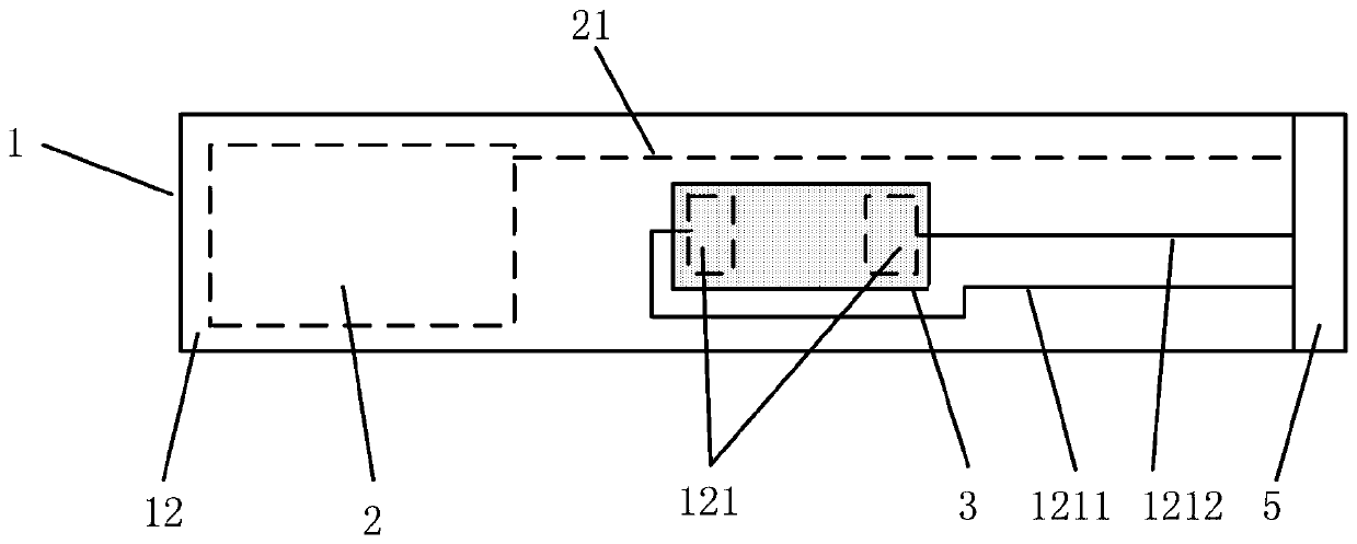
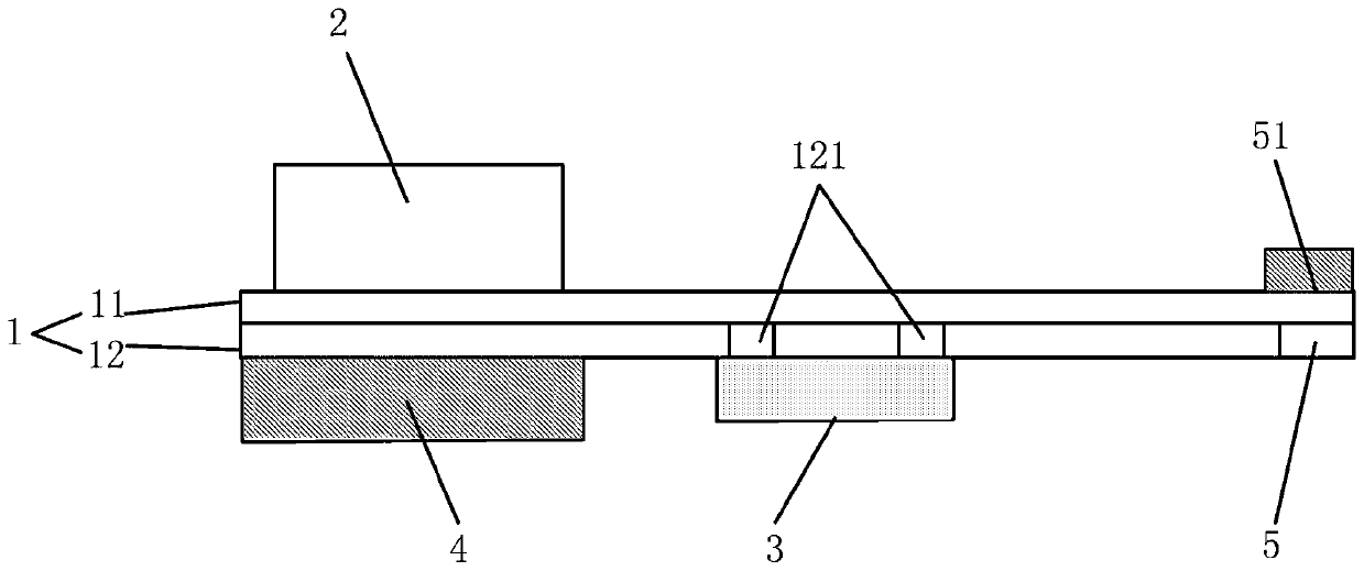
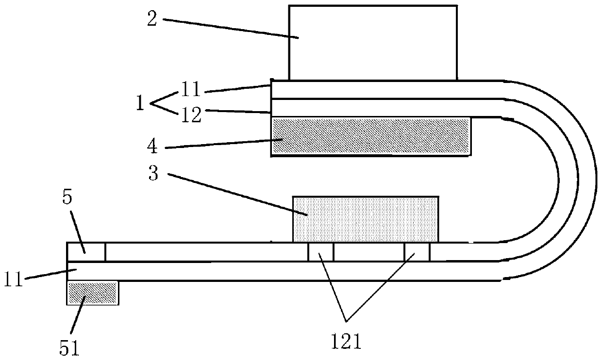
[0035] The first embodiment of the present invention relates to a fingerprint identification device, which is applied to electronic equipment, such as mobile phones, such as Figures 1 to 3 As shown, the fingerprint identification device includes: a flexible circuit board FPC 1 , a fingerprint identification chip 2 and a pressure sensing la...


PUM


Abstract

The embodiment of the present invention relates to the technical field of electronic products, and discloses an electronic device, a fingerprint identification device and a function activation method. In the embodiment of the present invention, the fingerprint identification device includes: a flexible circuit board FPC, a fingerprint identification chip, and a pressure sensing layer; the FPC includes a first wiring layer and a second wiring layer; the bottom surface of the fingerprint identification chip is fixed on the The first wiring layer; the bottom surface of the pressure sensing layer is fixed to the second wiring layer; wherein, when the FPC is in a bent state, the top surface of the pressure sensing layer corresponds to the fingerprint Identify the underside of the chip. The embodiment of the present invention also provides an electronic device and a function activation method; the embodiment of the present invention integrates the fingerprint identification chip and the pressure-sensing layer, so that the fingerprint identification device has a pressure-sensing function, and realizes the diversification of functions of the fingerprint identification device, and The space and materials are saved, and the structure is simple, which brings convenience to manufacturing.

Description

technical field [0001] The embodiments of the present invention relate to the technical field of electronic products, and in particular to an electronic device, a fingerprint identification device and a method for starting a function. Background technique [0002] Existing smart terminals such as mobile phones and tablet computers are widely used in people's daily life. Due to the portability and appearance requirements of smart terminals, the structural space is very limited. People have been committed to realizing more functions in a limited space. , to give users a better experience. Wherein, the fingerprint recognition device in the smart terminal enables the smart terminal to have a fingerprint recognition function, which provides convenience for people's life. [0003] A fingerprint identification device in an existing intelligent terminal has a fingerprint identification function. However, in the process of realizing the present invention, the inventors found the fo...

Claims


Application Information

Patent Timeline
Patent Type & Authority Patents(China)
IPC IPC(8): G06K9/00
CPCG06V40/1306G06V10/94
Inventor 叶金鑫
Owner HUAQIN TECH CO LTD
Learn More