
Mechanical overspeed protection device

An overspeed protection, mechanical technology, applied in safety devices, transportation and packaging, railway car body parts, etc., can solve the problems of rare, incompatible with no electricity, can not produce open flames, etc., and achieve the effect of high safety level

Active Publication Date: 2017-07-21
安徽中捷矿山运输设备有限责任公司
View PDF5 Cites 3 Cited by
  • Summary
  • Abstract
  • Description
  • Claims
  • Application Information

AI Technical Summary

Problems solved by technology

[0002] In the prior art, in the braking of mechanical rail cranes and mining vehicles, hydraulic braking systems are used for passive braking. However, there are few related protection devices for speed-limiting protection devices for cranes or mining vehicles in emergency situations. Device and technology research
Especially in the underground working conditions where mining vehicles are ubiquitous, for the general electronic overspeed protection device, because it needs to be charged to function, it does not meet the strict preconditions of no electricity and no open flames in the underground working environment. Require

Method used


Image

  • Mechanical overspeed protection device
  • Mechanical overspeed protection device

Examples


Embodiment Construction

[0021] In order to make the objectives, technical solutions and advantages of the present invention clearer, the following further describes the present invention in detail with reference to the accompanying drawings and embodiments. It should be understood that the specific embodiments described herein are only used to explain the present invention, but not to limit the present invention.

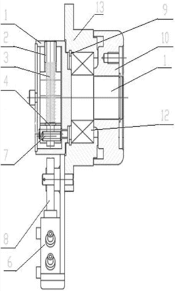
[0022] Such as figure 1 As shown, a mechanical overspeed protection device includes a housing 13, a wheel axle 1, and a hydraulic brake valve 6, and the wheel axle 1 passes through the housing 13;

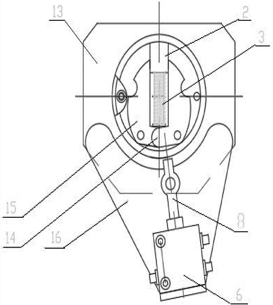
[0023] Such as figure 2 As shown, a cross section of one end of the wheel shaft 1 is provided with a left centrifugal block 15 and a right centrifugal block 14 movably provided by a pin shaft, see Appendix figure 1 As shown, the other end of the axle 1 is fixedly sleeved with a gear 10;

[0024] Such as Figure 1-2 As shown, a brake spring 3 is provided between the left and right centrifugal blocks ...


PUM


Abstract

The invention discloses a mechanical overspeed protection device. The mechanical overspeed protection device comprises a shell, a wheel shaft and a hydraulic brake valve; the wheel shaft is arranged in the shell in a penetrating mode; a left centrifugal block and a right centrifugal block are movably arranged on the cross section of one end of the wheel shaft through a pin shaft; a gear is fixedly arranged at the other end of the wheel shaft in a sleeving mode; a brake spring is arranged between the left centrifugal block and the right centrifugal block in the radial direction of the cross section of the wheel shaft; a polished pin is arranged at the lower end of the right centrifugal block; an adjusting nut used for adjusting the position of the brake spring is arranged at one end of the brake spring and is fixedly connected on the wheel shaft; a spring shaft is fixedly arranged at the other end of the brake spring; the spring shaft and the polished pin are clamped with each other; the hydraulic brake valve is fixedly arranged on the position, corresponding to the spring shaft, of the shell through a connecting plate; and the brake valve comprises a short swing rod used for controlling the hydraulic brake valve. According to the mechanical overspeed protection device, in order to ensure the speed limiting effect, when the clamping of the spring shaft and the polished pin is separated, the natural length of the spring shaft can ensure that the spring shaft completely abuts against the short swing rod, then the hydraulic brake valve is triggered to be started, and therefore a hydraulic braking system is started.

Description

Technical field [0001] The invention relates to the technical field of production and manufacture of mechanical brake devices, and is specifically applied to a brake device for overspeed protection of crane traveling rollers and mining vehicles, especially a mechanical overspeed protection device. Background technique [0002] In the prior art, in the braking of mechanical rail cranes and mining vehicles, hydraulic braking systems are used for passive braking. However, there are few relevant speed limit protection devices for cranes or mining vehicles in emergency situations. Device and technology research. Especially in underground working conditions where mining vehicles are common, general electronic overspeed protection devices need to be charged to function, which does not meet the strict pre-conditions of no electricity and no open flames in the underground working environment. Claim. [0003] Based on the requirements under the above application conditions, the present inv...

Claims


Application Information

Patent Timeline
IPC IPC(8): B66C15/00B61H11/04B61H11/06
CPCB61H11/04B61H11/06B66C15/00
Inventor 刘春蔡晓杰汤永红张武义邓前峰孟祥春董凯王洪波
Owner 安徽中捷矿山运输设备有限责任公司
Learn More