
A New Type of Landing Gear Buffer

A landing gear buffer, a new type of technology, applied in the direction of shock absorbers, shock absorbers, springs/shock absorbers, etc., can solve problems such as inability to meet work needs, and achieve the effect of enriching configurations

Active Publication Date: 2019-03-01
HARBIN
View PDF6 Cites 0 Cited by
  • Summary
  • Abstract
  • Description
  • Claims
  • Application Information

AI Technical Summary

Problems solved by technology

For some special configurations of landing gear, it cannot meet its working requirements

Method used


Image

  • A New Type of Landing Gear Buffer
  • A New Type of Landing Gear Buffer
  • A New Type of Landing Gear Buffer

Examples


specific Embodiment approach

[0016] DETAILED DESCRIPTION OF THE PREFERRED EMBODIMENTS: The present invention will be further described in detail below in conjunction with the accompanying drawings.

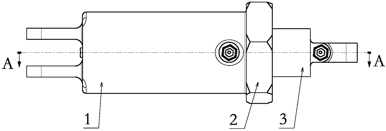
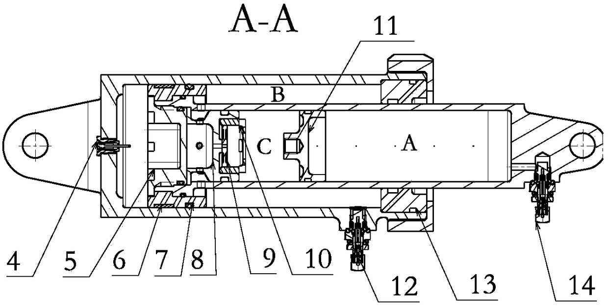
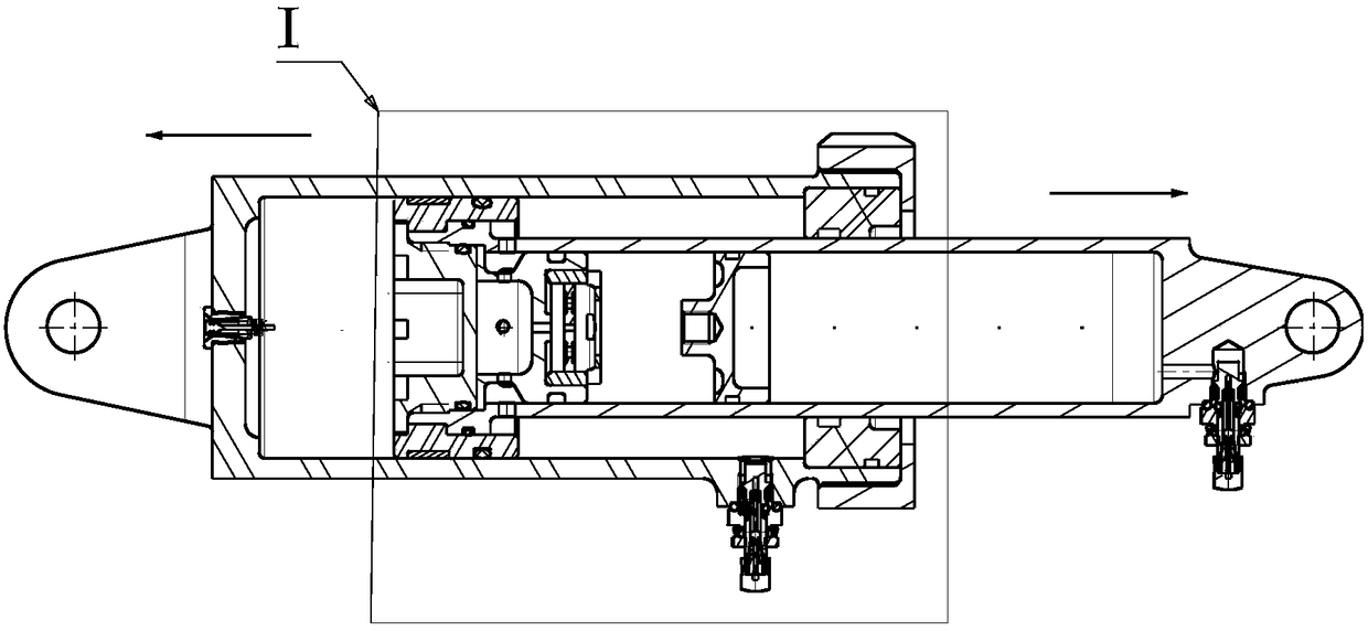
[0017] As shown in Figure 1, the structure of the present invention includes an outer cylinder 1, an outer nut 2, an inner cylinder 3, an exhaust nozzle 4, a pressing member 5, a wear-resistant ring 6, a slider 7, a damping plate 8, a valve 9, and a valve nut 10. Isolation piston 11, grease nozzle 12, support member 13, and inflation valve 14, wherein the isolation piston 11 is installed in the inner cylinder 3; the valve 9 is installed in the valve nut 10, and the valve nut 10 is tightened with the damping plate 8, and the damping plate 8 is installed in the inner cylinder 3; the wear-resistant ring 6 is installed in the outer groove of the slider 7, the slider 7 is installed outside the inner cylinder 3, and the pressing part 5 is tightened with the inner cylinder 3; the inner cylinder 3 is installed in the ...


PUM


Abstract

The invention discloses a novel landing gear bumper which comprises an outer barrel (1), an outer nut (2), an inner barrel (3), an exhaust nozzle (4), a pressing piece (5), a wear-resistant ring (6), a sliding block (7), a damping plate (8), a valve (9), a valve nut (10), an isolation piston (11), an oil injection nozzle (12), a supporting piece (13) and an air charging valve (14). Through arrangement adjustment of an oil-gas cavity and brand new design of the structural form, the bumper with the contrary work manner of a conventional bumper is achieved. The bumper is in the shortest state when being not borne with an external load, the bumper extends when being borne with the external load, the structure of a landing gear is enriched, and a technical foundation is provided for meeting special requirements of airplanes.

Description

technical field [0001] The invention belongs to the technical field of aircraft structure design and relates to a novel landing gear buffer. Background technique [0002] Conventional landing gear buffers are in a compressed state when the aircraft lands; after the aircraft takes off the ground, the buffers are in a fully extended state. For the landing gear of some special configurations, it cannot meet its working requirements. [0003] The working mode of the landing gear buffer studied by the present invention is opposite to that of conventional buffers. When the aircraft lands and receives ground loads, the buffer is in an elongated state; when the aircraft takes off, the buffer is in a compressed state. Contents of the invention [0004] Purpose of the present invention: the novel buffer provided by the present invention can meet the needs of special landing gear, and provides technical possibilities for the configuration development of the landing gear. [0005] T...

Claims


Application Information

Patent Timeline
Patent Type & Authority Patents(China)
IPC IPC(8): F16F9/32F16F9/34
CPCF16F9/3207F16F9/34F16F2222/12
Inventor 季茂龄邓云生程迪迪董哲
Owner HARBIN
Learn More