A self-telescopic landing gear buffer

A technology of landing gear buffers and buffers, which is applied in the direction of landing gears, shock absorbers, shock absorbers, etc., can solve problems such as inability to meet special tasks, and achieve the effect of enriching configurations

Active Publication Date: 2018-08-24
哈尔滨哈飞航空工业有限责任公司
View PDF6 Cites 0 Cited by
  • Summary
  • Abstract
  • Description
  • Claims
  • Application Information

AI Technical Summary

Problems solved by technology

In view of the passive working mode of the existing landing gear, which cannot meet the needs of special tasks, there is an urgent need for an autonomously retractable landing gear buffer

Method used


Image

  • A self-telescopic landing gear buffer
  • A self-telescopic landing gear buffer
  • A self-telescopic landing gear buffer

Examples


specific Embodiment approach

[0014] DETAILED DESCRIPTION OF THE PREFERRED EMBODIMENTS: The present invention will be further described in detail below in conjunction with the accompanying drawings.

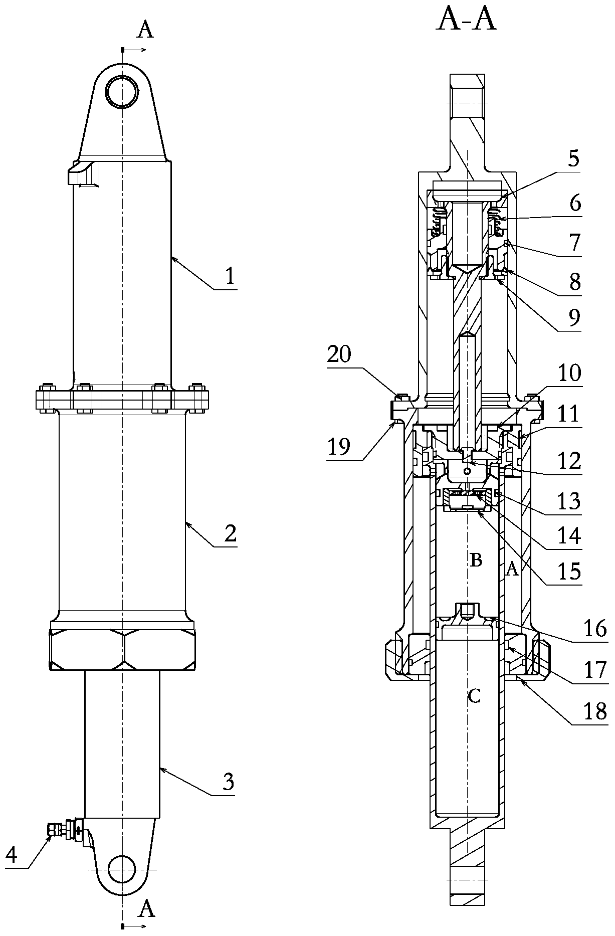
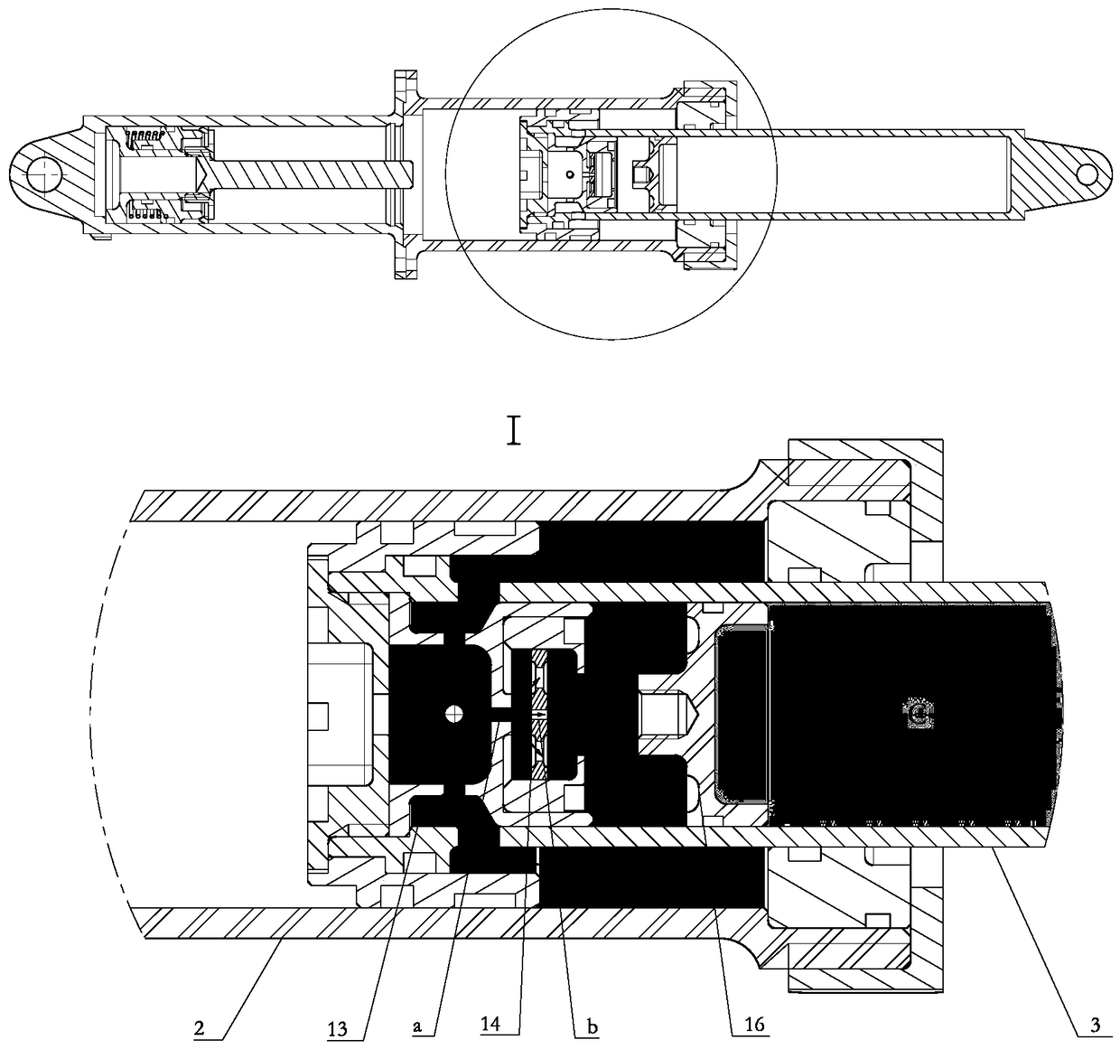
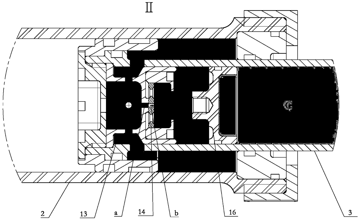
[0015] The operating principle of the buffer of the present invention is:

[0016] Elongation energy absorption: when the buffer is elongated, the volume of oil chamber 1A decreases, the oil in chamber A pushes away from the valve 14 at high speed and flows into oil chamber 2B through the positive damping hole a on the damping plate 13, and the oil in chamber B increases , pushing the isolation piston 16 to move downward, forcing the volume of the air chamber C to decrease and the pressure to increase. During this process, the buffer converts the kinetic energy of the helicopter into the kinetic energy of the oil and the elastic potential energy of the gas, while the high-speed flowing oil rubs against the positive damping hole a on the damping plate 13 to generate heat, and finally passes through the inner a...


PUM


Abstract

The invention discloses an independent telescopic landing gear bumper, comprising a mechanism outer cylinder 1, a bumper outer cylinder 2, a bumper inner cylinder 3, a charging valve 4, a mechanism ejector rod 5, a mechanism spring 6, a mechanism piston 7, a clamping block 8, a connecting nut 9, a bumper nut 10, a bumper piston 11, an oil plug 12, a damping plate 13, a valve 14, a valve nut 15, a separator piston 16, a bumper screw cap 17, a bumper nut 18, a bolt 19, and a nut 20. According to the invention, an executing mechanism is integrally designed on the bumper to control elongation and contraction of the bumper, thereby achieving squatting and uplifting of a landing gear. The executing mechanism has a function of locking and unlocking at a maximum extending position through hydraulic driving. A novel landing gear bumper is realized, the configuration of the landing gear is enriched, and a technical basis is provided for meeting specific requirements of a plane.

Description

technical field [0001] The invention belongs to the technical field of aircraft structure design and relates to an autonomous retractable landing gear buffer. Background technique [0002] The existing landing gear buffers all work in a passive telescopic mode, that is, when the wheels are subjected to loads from the ground, the buffers are in different compression (or elongation) states according to the size of the load; , the buffer is in a fully extended (or shortened) state. In view of the passive working mode of the existing landing gear, which cannot meet the needs of special tasks, there is an urgent need for an autonomously retractable landing gear buffer. Contents of the invention [0003] Purpose of the present invention: the landing gear buffer studied by the present invention can reach the limit of the stroke through hydraulic drive, so that the landing gear has the function of squatting on the ground, which is convenient for cargo transportation and personnel...

Claims


Application Information

Patent Timeline
Patent Type & Authority Patents(China)
IPC IPC(8): F16F9/06F16F9/32F16F9/56B64C25/58B64C25/60
Inventor 季茂龄邓云生程迪迪董哲
Owner 哈尔滨哈飞航空工业有限责任公司
Why Eureka
Try Eureka