A Reconfigurable Machine Tool Based on Reconfigurability

A reconfigurable and machine tool technology, applied in the direction of metal processing equipment, metal processing, manufacturing tools, etc., can solve the problems of low cost, difficult RMT reconfiguration, waste of equipment and other resources, so as to reduce the cost of reconfiguration and achieve reliable High refactorability and refactoring stability

Active Publication Date: 2019-08-16
BEIJING INSTITUTE OF TECHNOLOGYGY
View PDF6 Cites 0 Cited by
  • Summary
  • Abstract
  • Description
  • Claims
  • Application Information

AI Technical Summary

Problems solved by technology

[0007] (1) The design based on traditional RMT / RMS design principles (such as Katz’s design principles) around a specific workpiece family is difficult to meet the processing requirements of another workpiece family through reconstruction, resulting in waste of resources such as equipment and deviation from The original intention of reconfigurable (low cost)
[0008] (2) The RMT of the overall structure is the practice of traditional design principles, among which the arch-type is the pinnacle of the RMT of the overall structure, but there is still no way to avoid the processing requirements of a single workpiece family and the lack of richness of the machine tool configuration Defects
[0009] (3) The RMT based on the module structure is more flexible than the overall structure, but the various module division methods, the module combination is too complicated, and the RMT reconstruction is difficult
In addition, low module reuse rate is also one of the problems that the module structure RMT needs to solve

Method used


Image

  • A Reconfigurable Machine Tool Based on Reconfigurability
  • A Reconfigurable Machine Tool Based on Reconfigurability
  • A Reconfigurable Machine Tool Based on Reconfigurability

Examples


Embodiment 1

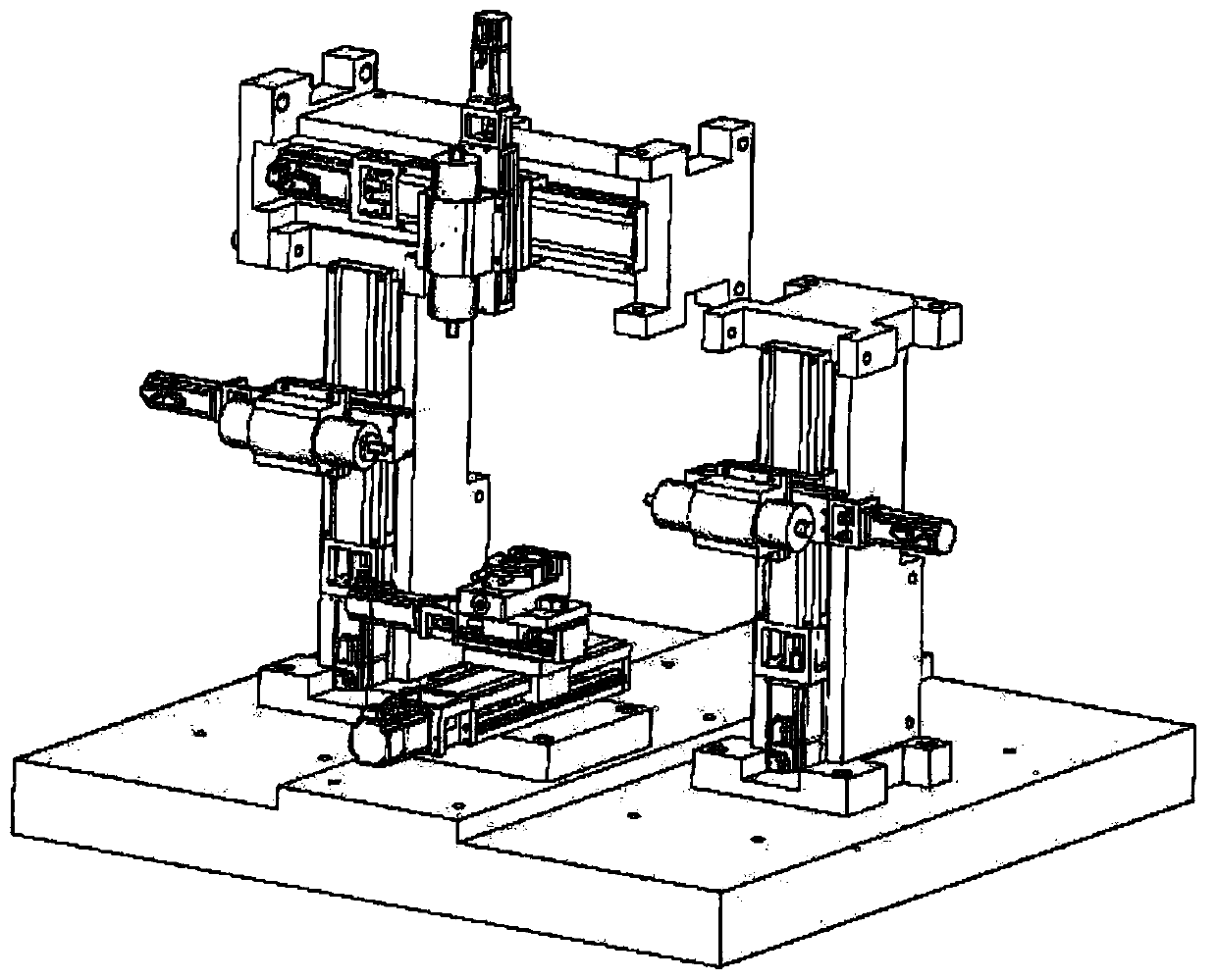
[0046]Based on the above design principles, the embodiment of the present invention provides a reconfigurable machine tool based on reconfigurability, its specific structure is as follows figure 1 As shown, the designed modules include bed module, functional arm module and workbench module.

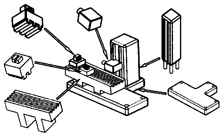
[0047] image 3 It shows the structure of the bed module. The bed module is a rectangular flat structure, which is divided into three areas by two parallel boundaries, which are respectively the installation area of ​​the workbench module in the center and the first functional arm on both sides. The module installation area and the second functional arm module installation area; the positional relationship of the three areas is as follows image 3 shown.

[0048] according to image 3 , the three regions are equipped with pairs of threaded holes equidistantly distributed at a distance of l units, and each pair of threaded holes is composed of two threaded holes with a distance of l uni...


PUM


Abstract

The invention discloses a reconfigurable machine tool based on reconfigurability. According to the structure of the reconfigurable machine tool based on reconfigurability, a machine tool body module comprises a workbench module installation area located in the center, a first functional arm installation area and a second functional arm installation area, wherein the first functional arm installation area and the second functional arm installation area are installed on the two sides; the three areas are all provided with threaded hole pairs; the functional arm module comprises a stand column and a functional assembly, wherein the side face of the stand column is provided with a guide rail, the side face opposite to the guide rail is fixedly provided with a convex block, the convex block isprovided with a threaded hole, the upper end face and the lower end face of the stand column are both provided with bosses, the four corners of each boss are provided with threaded holes, the functional assembly is a customized piece used for machining an original equipment manufacturing workpiece and connected to the guide rail in a sliding manner; and the workbench module comprises a base and aclamp. According to the connection relationship, the threaded holes in the first functional arm module installation area or the second functional arm module installation area are matched and installedwith the four threaded holes formed in the boss of the lower end face of the functional arm module, and threaded holes in the workbench module installation area are matched and installed with the threaded holes formed in the four corners of the base of the workbench module.

Description

technical field [0001] The invention relates to the technical field of advanced manufacturing, in particular to a reconfigurable machine tool based on reconfigurability. Background technique [0002] Reconfigurable Manufacturing System (RMS) can provide precise processing functions and processing capabilities in a low-cost and fast-response manner according to customer requirements to meet changing market demands, and has gradually become a research hotspot. [0003] Reconfigurable machine tools (RMT) is the key equipment of RMS. RMT-related research is the key link in the realization of RMS, and RMT prototype design is the basic research of RMT, and RMT design principles provide principled and directional guidance for prototype design. [0004] At the beginning of the design, RMS is determined to quickly respond to sudden changes in the requirements of a certain workpiece family, and to design or select corresponding machine tools (CNC machine tools and / or RMT) to process ...

Claims


Application Information

Patent Timeline
Patent Type & Authority Patents(China)
IPC IPC(8): B23Q37/00
CPCB23Q37/002B23Q37/007
Inventor 黄思翰王国新阎艳曾聪王思明
Owner BEIJING INSTITUTE OF TECHNOLOGYGY
Why Eureka
Try Eureka