3D four-wheel position indicator for intelligently capturing target image and control method thereof

A technology of four-wheel aligner and target target, which is applied in the direction of using feedback control, program control, computer control, etc., and can solve problems such as low operating efficiency and inaccurate positioning effect

Pending Publication Date: 2017-07-21
桂林施瑞德科技发展有限公司
View PDF8 Cites 3 Cited by
  • Summary
  • Abstract
  • Description
  • Claims
  • Application Information

AI Technical Summary

Problems solved by technology

[0004] What the present invention aims to solve is the problem of low operating efficiency and inaccurate positioning effect caused by the need for repeated adjustments and lifting of the existing 3D four-wheel aligner. It provides a 3D four-wheel aligner that intelligently captures target images and its control method

Method used


Image

  • 3D four-wheel position indicator for intelligently capturing target image and control method thereof
  • 3D four-wheel position indicator for intelligently capturing target image and control method thereof
  • 3D four-wheel position indicator for intelligently capturing target image and control method thereof

Examples


Embodiment 1

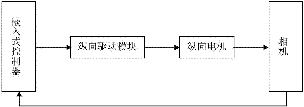
[0044] A 3D four-wheel aligner that intelligently captures target images, such as figure 1 As shown, it is mainly composed of target target, camera, camera beam, camera column, lift and camera control components. The camera control assembly includes a vertical motor, a vertical drive module and an embedded controller. The target is mounted on the wheel hub of the car to be tested. The car to be tested is on the ground or on a lift. In order to realize the automatic adjustment of the shooting height of the camera, in this embodiment, the camera is fixedly installed on the camera beam, and the camera beam is movably installed on the camera column. The camera, the camera beam and its camera column can be arranged at the front end of the lift together, and can also be arranged at the rear end of the lift together. However, in order to facilitate the entry of the wheels to be detected, in this embodiment, the camera, the camera beam and its camera post can be co-located on the f...

Embodiment 2

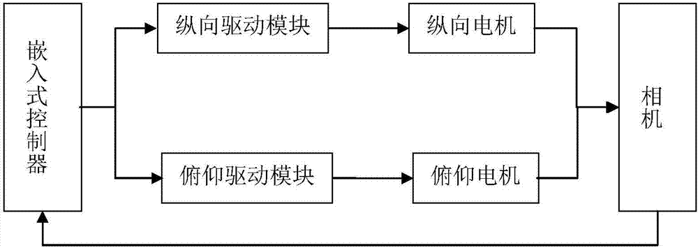
[0057] Embodiment 2 is further improved on the basis of Embodiment 1. Embodiment 1 can only realize the vertical height adjustment of the camera, that is, the camera is fixedly installed on the camera beam, and the camera beam is movably installed on the camera column. However, Embodiment 2 can not only realize the vertical height adjustment of the camera, but also can realize the vertical pitch angle adjustment of the camera, that is, the camera control assembly further includes a pitch motor and a pitch drive module. The camera is installed on the camera beam through the pitching bracket, and can perform pitching motion on the camera beam under the drive of the pitching motor. The pitch control output end of the embedded controller is connected to the pitch motor via the pitch drive module.

[0058] Specifically, a 3D four-wheel aligner that intelligently captures target images, such as figure 2 As shown, it is mainly composed of target target, camera, camera beam, camera ...

Embodiment 3

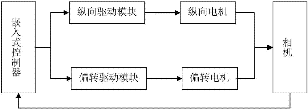
[0064] Embodiment 3 is further improved on the basis of Embodiment 1. Embodiment 1 can only realize the vertical height adjustment of the camera, that is, the camera is fixedly installed on the camera beam, and the camera beam is movably installed on the camera column. However, Embodiment 3 can not only realize the vertical height adjustment of the camera, but also can realize the horizontal deflection angle adjustment of the camera, that is, the camera control assembly further includes a deflection motor and a deflection drive module. The camera is installed on the camera beam through the deflection bracket, and can perform deflection movement on the camera beam under the drive of the deflection motor. The deflection control output end of the embedded controller is connected to the deflection motor via the deflection drive module.

[0065] Specifically, a 3D four-wheel aligner that intelligently captures target images, such as image 3 As shown, it is mainly composed of targ...


PUM


Abstract

The invention discloses a 3D four-wheel position indicator for intelligently capturing a target image and a control method thereof. The 3D four-wheel position indicator comprises a target, a camera, a camera crossbeam, a camera column, a lifting machine and a camera control component. The target is installed on the wheel hub of an automobile to be detected. The camera is installed on the camera crossbeam which is installed on the camera column. The camera, the camera crossbeam and the camera column are arranged on the front end and / or the rear end of the lifting machine and the camera faces the direction of the lifting machine. Adaptive adjustment of the position and the angle of the camera can be realized by the camera control component so that the measurement process is enabled to be performed on the ground. If chassis parameters require to be adjusted after all the measurement is completed, only the lifting machine requires to be lifted to any position facilitating operation of the worker, and the camera crossbeam assembly intelligently elevates to search the target and automatically and accurately capture and identify the target so that the objectives of being time-saving, labor-saving, cost-saving, efficient and accurate can be achieved through accurate adjustment and measurement.

Description

technical field [0001] The invention relates to the technical field of four-wheel alignment, in particular to a 3D four-wheel alignment device for intelligently capturing target images and a control method thereof. Background technique [0002] Correct positioning of the wheels can make the car safer to handle, more comfortable to ride, and can maximize the service life of the car tires. The working process of the existing 3D four-wheel aligner is as follows: first, install the target target on the wheel hub of the car to be detected; and fix the camera beam on the camera column to fix the position and height of the camera so that the camera can be used throughout the measurement Do not move during the process; then, drive the car on the lift, the lift drives the car to a certain height, and enables the camera to capture the target image on the wheel hub; after that, let the car lift at this height Cart on board for measurement. After the measurement, if it is necessary to...

Claims


Application Information

Patent Timeline
IPC IPC(8): G01B11/275G05D3/12G05B19/042
CPCG05B19/042G05B19/0426G05D3/12G01B11/275G01B2210/14G05B2219/23258G05B2219/25257G05B2219/2651G01B11/2755
Inventor 黄雄文唐文帅唐永红马艳华俸耀明阳永春区杨甘泉
Owner 桂林施瑞德科技发展有限公司
Why Eureka
Try Eureka