Infeed Tool

A cutting tool and feed technology, which is applied to milling cutters, manufacturing tools, metal processing equipment, etc., can solve the problems of unguaranteed processing coaxiality, low roughness of the processing surface, and affecting processing accuracy, etc., to achieve convenient and fast processing and manufacturing. The effect of simple and fast grinding and smooth cutting process

Active Publication Date: 2020-04-28
JIANGSU ROKEE HEAVY IND TECH
View PDF7 Cites 0 Cited by
  • Summary
  • Abstract
  • Description
  • Claims
  • Application Information

AI Technical Summary

Problems solved by technology

[0002] In the prior art, the tools used to process inner holes such as keys and grooves generally use the slotting tool to pull and mill the inner hole of the keyway. The keyway is processed by pulling and pulling; the diameter of the tool bar of the inserting tool must be smaller than the diameter of the inner hole of the workpiece, and the tool bar is suspended to form a cantilever beam structure, resulting in poor rigidity of the tool bar. The processing coaxiality cannot be guaranteed, and the adjustment is difficult. The workpiece needs to be adjusted and positioned repeatedly before processing, and the processing efficiency is low. Moreover, it is difficult to process blind holes, stepped holes, and inner groove surfaces on the inner surface of the workpiece with traditional slotting tools.

Method used


Image

  • Infeed Tool

Examples


Embodiment Construction

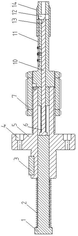
[0010] As shown in the figure, an internal feed tool includes a tool seat 5 for connecting the special machine tool spindle and the processing tool, and can quickly replace the tool holder. The tool seat 5 is installed on the tool seat screw hole 4 on the flange On the fixed seat of the special machine tool spindle, the positioning key 3 is used for positioning and installation when installing and fixing. The tool seat positioning key 3 is used to ensure the installation position of the tool seat 5 and the special machine tool spindle, and the tool seat 5 passes through; the center of the tool seat 5 has a through hole, and the through hole A knife bar 13 is arranged inside the front section, and the knife bar 13 is fixedly connected to the front section of the tool holder 5 through the knife bar locking member 7; The outer peripheral surface of the shaft shoulder has a fastening external thread, and the outer peripheral surface of the front section of the tool seat 5 also has ...


PUM


Abstract

The invention provides an internal feeding tool. A tool bar is fixedly connected into the front section of a central through hole in a tool seat through a tool bar locking part. A tool bit is arranged in a radial groove in the front section of a central hole in the tool bar. A guiding slope at the inner end of the tool bit is matched with a tool bar ejector rod penetrating into the central hole of the tool bar to enable the tool bar ejector rod to push the tool bit to stretch out of the tool bar along the radial groove. The front section of the tool bar is sleeved with a tool bar guiding sleeve with the outer diameter being adaptive to the inner hole size of a machined workpiece. Tool feeding precision is high, and the cutting process is stable. The tool bar is inserted into a hole of the workpiece to be machined and is positioned through the tool bar guiding sleeve, repeated adjustment of the concentricity is not needed, and positioning is convenient. The guiding sleeve enables the moving track of the tool bar relative to the machined workpiece to be stable, machining precision is high, the levelness of a machined surface is good, and key groove machining symmetry is improved. The tool cost is low, machining and manufacturing is convenient and rapid, and the tool can be suitable for different machining hole diameters and key groove widths and can machine arc grooves and spiral grooves in blind holes and stepped holes.

Description

technical field [0001] The invention relates to an inner feed tool. Background technique [0002] In the prior art, the tools used to process inner holes such as keys and grooves generally use the slotting tool to pull and mill the inner hole of the keyway. The keyway is processed by pulling and pulling; the diameter of the tool bar of the inserting tool must be smaller than the diameter of the inner hole of the workpiece, and the tool bar is suspended to form a cantilever beam structure, resulting in poor rigidity of the tool bar. The processing coaxiality cannot be guaranteed, and the adjustment is difficult. It is necessary to repeatedly adjust and position the workpiece before processing. The processing efficiency is low, and the traditional slotting tool is difficult to process blind holes, stepped holes, and inner groove surfaces on the inner surface of the workpiece. Contents of the invention [0003] The technical problem to be solved by the present invention is t...

Claims


Application Information

Patent Timeline
Patent Type & Authority Patents(China)
IPC IPC(8): B23C3/34B23C5/12
CPCB23C3/34B23C5/12
Inventor 石光洲尤忠
Owner JIANGSU ROKEE HEAVY IND TECH
Why Eureka
Try Eureka