Wind power generation device

An energy power generation and wind power technology, which is applied to wind power generation, wind turbines, and wind turbines in the same direction as the wind, can solve the problems of tight power supply to users, low wind resistance performance of devices, and difficulty in installing large-scale wind power generation devices. High wind resistance, quick installation effect

Inactive Publication Date: 2019-04-26
NANJING POLYTECHNIC INSITUTE
View PDF0 Cites 0 Cited by
  • Summary
  • Abstract
  • Description
  • Claims
  • Application Information

AI Technical Summary

Problems solved by technology

[0005] The purpose of the present invention is to provide a wind energy power generation device to solve the problem that the existing farming shedhouses proposed in the above background technology are far away from the power supply area and subject to the influence of weather conditions, and the solar panels cannot provide timely power supply in rainy days. As a result, the power supply of users is relatively tight. At the same time, greenhouse growers are generally located in relatively remote locations. It is difficult to install large-scale wind power generation devices, and there are problems and deficiencies in the device's low wind resistance.

Method used


Image

  • Wind power generation device
  • Wind power generation device
  • Wind power generation device

Examples


Embodiment approach

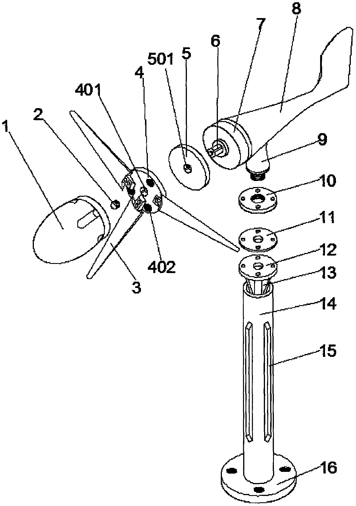
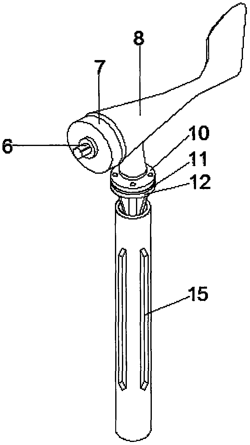
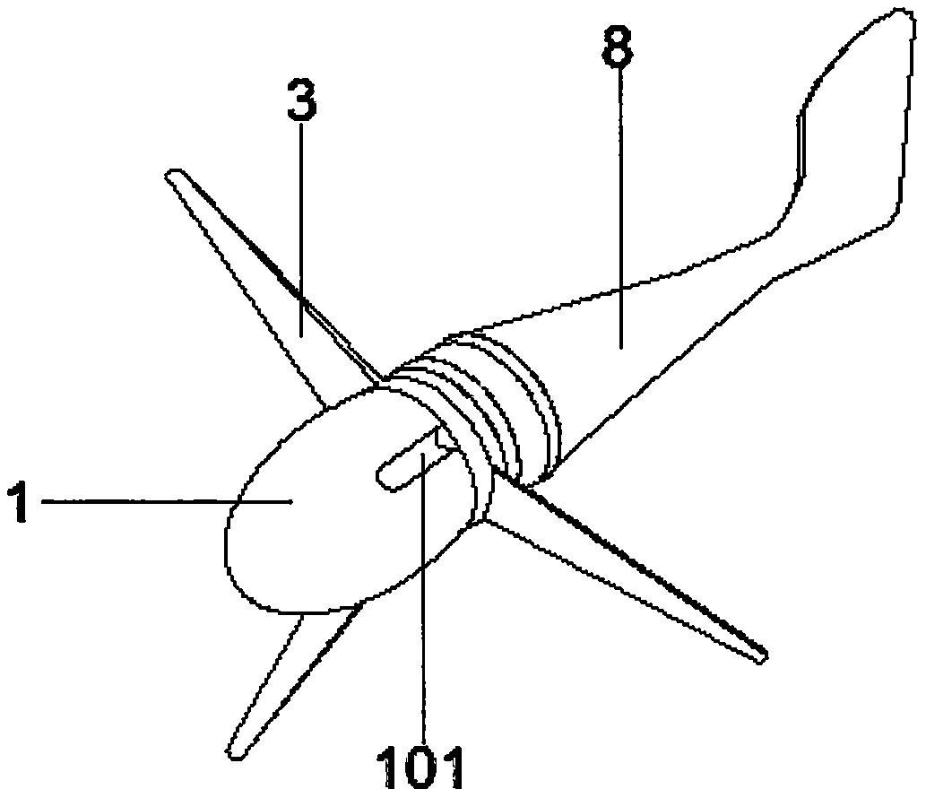
[0028] A wind energy power generation device, comprising: fairing 1, nut 2, blade 3, wind wheel hub 4, wheel seat 5, wind turbine shaft 6, wind wheel 7, body 8, connecting seat 9, flange seat 10, rubber pad 11. The second flange seat 12, the reinforcing block 13, the column 14, the reinforcing rib 15, the chassis 16, the internal threaded hole 101, the through hole 401, the threaded hole 402 and the second through hole 501; the wind wheel 7 is arranged in the body 8 The front part, and the wind wheel 7 and the main body 8 are connected by interference; the wind turbine shaft 6 is arranged in the middle of the front part of the wind wheel 7, and the wind turbine shaft 6 and the wind wheel 7 are connected in a movable manner; the wind turbine shaft 6 A wind wheel hub 4 and a wheel seat 5 are arranged on the outside of the wind turbine, and the wind turbine shaft 6 is connected with the wind wheel hub 4 and the wheel seat 5 in a through way; the nut 2 is arranged at the front outer...


PUM


Abstract

The invention provides a wind power generation device which comprises fan blades, a fan wheel hub and a wind wheel shaft. A wind wheel is arranged on the front part of a main body, and the wind wheelis connected with the main body in a interference connection mode. The wind wheel shaft is arranged in the middle of the front part of the wind wheel, and the wind wheel shaft is movably connected with the wind wheel. The wind wheel hub and a wheel seat are arranged outside the wind wheel shaft, and the wind wheel shaft is connected with the wind wheel hub and the wheel seat in a penetrating mode.A nut is arranged at the outer end of the front part of the wind wheel shaft, and the nut is rotationally connected with the wind wheel shaft. The fan blades are arranged on the front part of the wind wheel hub, and the fan blades are connected with the wind wheel hub through bolts in a fastened mode. A through hole is formed in the middle of the interior of the wind wheel hub. By improving the structure and combining with the existing technology, the device has the advantages of being high in wind resistance performance and small in size and can be installed rapidly, problems and deficiencies in the prior device technology are solved, and the purpose of higher practicability is achieved.

Description

Technical field [0001] The invention relates to the technical field of wind power generation, and more specifically, to a wind energy power generation device. Background technique [0002] Wind power generation refers to the conversion of kinetic energy of wind into electric energy; wind energy is a clean and pollution-free renewable energy source, which has been used by people very early, mainly through windmills to pump water and grind noodles. Now, people are interested It is how to use the wind to generate electricity; the use of wind power is very environmentally friendly and has a huge amount of wind energy, so it is increasingly valued by countries all over the world. [0003] Through observation, it is found that because the existing farming huts are far away from the power supply area and are affected by the weather conditions, solar panels cannot provide electricity in time on cloudy and rainy days, resulting in a tight power supply for users. At the same time, there are ...

Claims


Application Information

Patent Timeline
Patent Type & Authority Applications(China)
IPC IPC(8): F03D1/00F03D1/06F03D1/04
CPCF03D1/00F03D1/04F03D1/0633F03D1/065F03D1/0691F03D1/0675Y02E10/72
Inventor 袁和荣
Owner NANJING POLYTECHNIC INSITUTE
Why Eureka
Try Eureka