
Liquid crystal display panel and liquid crystal display

A liquid crystal display panel and liquid crystal layer technology, applied in the direction of instruments, nonlinear optics, optics, etc., can solve the problems of color drift, different light colors, etc., and achieve the effect of improving color drift and small difference

Inactive Publication Date: 2017-07-28
SHENZHEN CHINA STAR OPTOELECTRONICS SEMICON DISPLAY TECH CO LTD
View PDF6 Cites 6 Cited by
  • Summary
  • Abstract
  • Description
  • Claims
  • Application Information

AI Technical Summary

Problems solved by technology

Therefore, the thickness of the liquid crystal corresponding to the RGB three-color light and the wavelength of the RGB three-color light are different. When squinting, the ratio of the three-color light is different from that of the front view, which will make the color of the mixed light different, that is, color drift.

Method used


Image

  • Liquid crystal display panel and liquid crystal display
  • Liquid crystal display panel and liquid crystal display
  • Liquid crystal display panel and liquid crystal display

Examples


Embodiment Construction

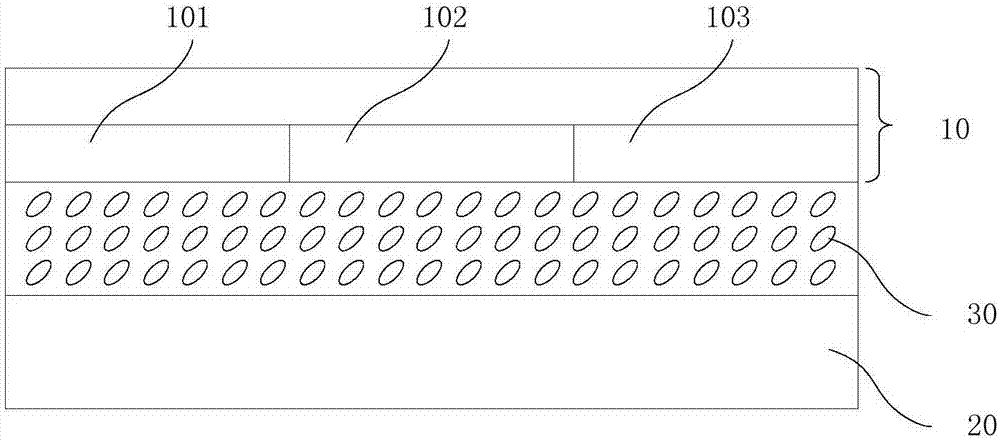
[0013] refer to figure 1 , figure 1 It is a structural schematic diagram of the first embodiment of the liquid crystal display panel provided by the present invention. The liquid crystal display panel includes an upper substrate 10 , a lower substrate 20 and a liquid crystal layer 30 between the upper substrate 10 and the lower substrate 20 .

[0014] Optionally, the lower substrate 20 may be a TFT array substrate, the upper substrate 10 may be a color filter substrate, and an electric field is formed between the transparent electrodes in the upper substrate 10 and the transparent electrodes in the lower substrate 20 to control the liquid crystal molecules in the liquid crystal layer 30 deflection.

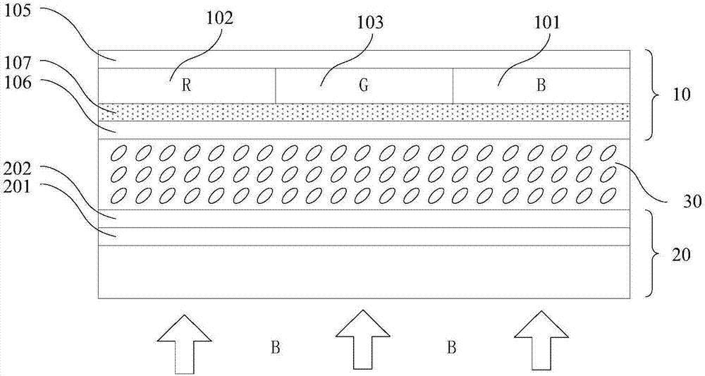
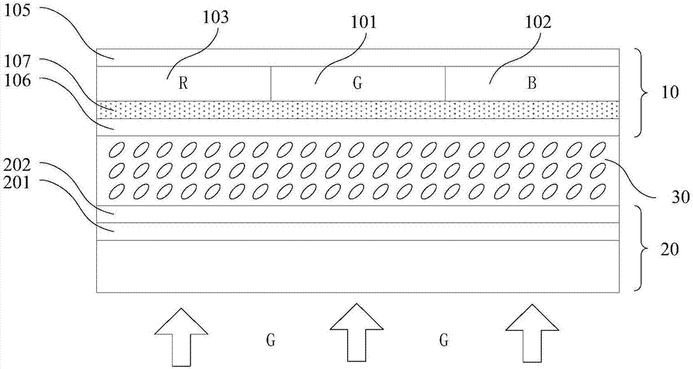
[0015] The liquid crystal display panel also includes a first film layer 101 , a second film layer 102 and a third film layer 103 respectively disposed on the upper substrate 10 corresponding to different regions. Wherein, the first film layer 101 is used to at least partially t...


PUM


Abstract

The invention discloses a liquid crystal display panel and a liquid crystal display. The liquid crystal display panel comprises an upper base plate, a lower base plate and a liquid crystal layer arranged between the upper base plate and the lower base plate, the liquid crystal display panel further comprises a first film layer, a second film layer and a third film layer respectively arranged on different corresponding regions of the upper base plate, the first film is used for passing at least part of the first color light incident from the lower base plate, the second film is used for converting the first color light incident from the lower base plate into the second color light, the third film is used for converting the first color light incident from the lower base plate into the third color light, wherein the thicknesses of the liquid crystal layer corresponding to the regions of different film layers are the same. Through the above arrangements, the liquid crystal display panel and the liquid crystal display can in a skewed angle of view make the three color ratios to have smaller differences with the front-facing ratios, and the color drifting is greatly improved.

Description

technical field [0001] The invention relates to the field of display technology, in particular to a liquid crystal display panel and a liquid crystal display. Background technique [0002] A liquid crystal display device is composed of an electrical control part and a light control part. Among them, the electric control part is composed of semiconductor TFT and conductive wiring part; the main working principle of the light control part is as follows: after the white light is polarized by the polarizer, the phase is changed by the liquid crystal, and the transparent electrode controls the direction of the liquid crystal, thereby controlling the degree of phase change , After being filtered by the filter film, and then analyzed by the polarizer, the RGB (red, green and blue) light has different transmittances, and the mixed colors are displayed (transmitted) by different lights. After forming an array, the image can be displayed. [0003] However, due to the different wavele...

Claims


Application Information

Patent Timeline
Patent Type & Authority Applications(China)
IPC IPC(8): G02F1/1335G02F1/1343
CPCG02F1/133514G02F1/1343
Inventor 陈剑鸿
Owner SHENZHEN CHINA STAR OPTOELECTRONICS SEMICON DISPLAY TECH CO LTD
Learn More