Liquid discharge apparatus and method
一种液体、液滴的技术,应用在液体喷出装置领域,能够解决影响喷嘴的墨水喷出性能、墨水附着等问题
- Summary
- Abstract
- Description
- Claims
- Application Information
AI Technical Summary
Problems solved by technology
Method used
Image

Examples
no. 1 Embodiment approach
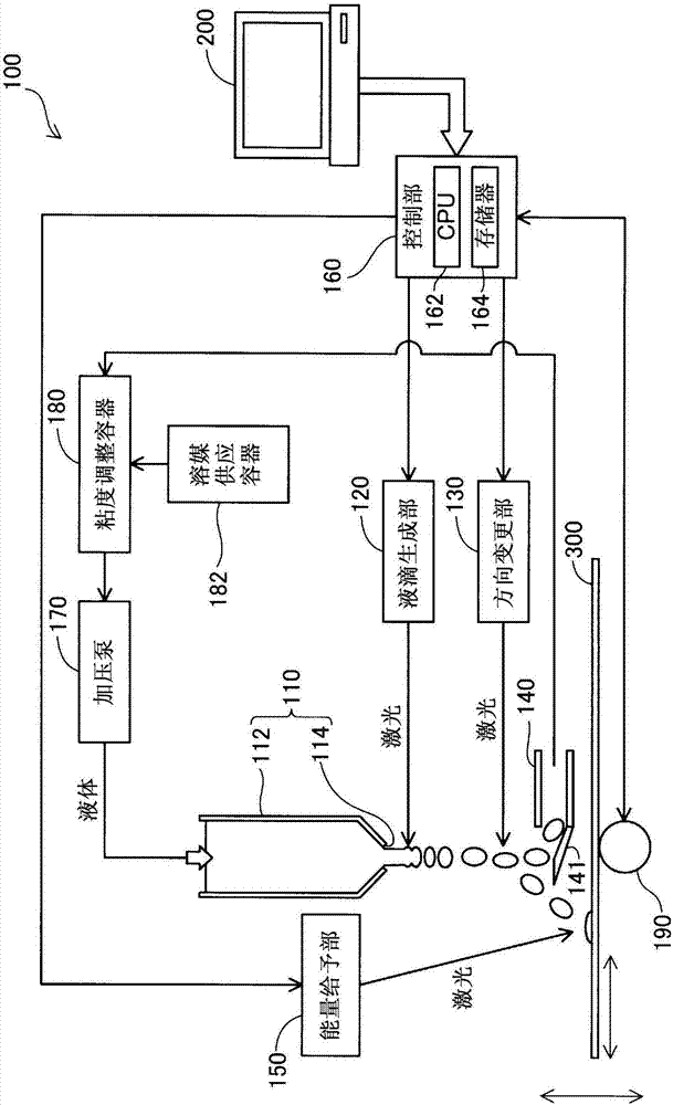
[0033] figure 1 It is an explanatory diagram showing a schematic configuration of the liquid ejection device 100 according to the first embodiment of the present invention. The liquid ejection device 100 includes a head 110 , a droplet generating unit 120 and a direction changing unit 130 . In addition, the ejection device of this embodiment includes a recovery unit 140 , an energy supply unit 150 , a control unit 160 , a pressure pump 170 , a viscosity adjustment container 180 , a solvent supply container 182 , and an object moving mechanism 190 .
[0034] The head 110 is provided with a nozzle 114 that ejects a liquid columnar liquid. Specifically, the head 110 includes a syringe 112 serving as a liquid container storing liquid, and a nozzle 114 communicating with the inside of the syringe 112 and ejecting the liquid in the syringe 112 to the outside. In this embodiment, the syringe 112 is cylindrical and formed of stainless steel. In addition, the nozzle 114 is formed as...
no. 2 Embodiment approach
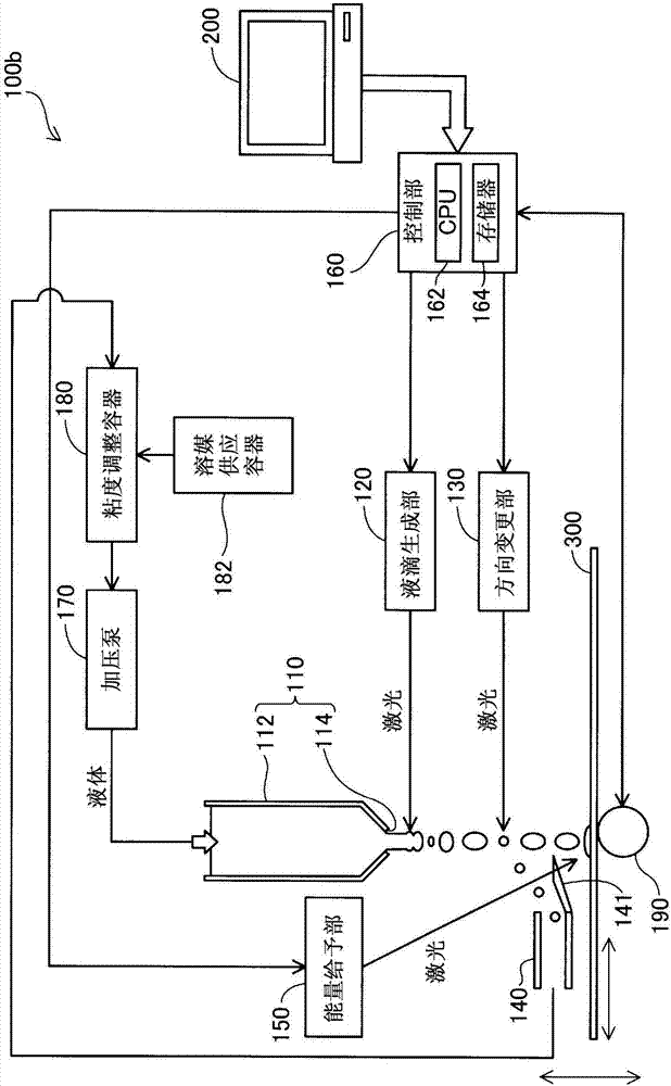
[0051] image 3 It is an explanatory diagram showing a schematic configuration of a liquid ejection device 100 b according to a second embodiment of the present invention. The configuration of the liquid ejection device 100b of the present embodiment is the same as that of the liquid ejection device 100 of the first embodiment. This embodiment is different from the first embodiment in that droplets of two sizes are generated by the droplet generating unit 120 . In this specification, the so-called droplet size refers to the volume of the droplet. In addition, the size of the liquid droplet can also be grasped as the weight of the liquid droplet.
[0052] The droplet generating unit 120 of the present embodiment generates droplets of a first size and droplets of a second size larger than the first size from the columnar liquid. The control unit 160 controls the droplet generating unit 120 so that the irradiation interval of the laser beam irradiating the liquid column is dif...
no. 3 Embodiment approach
[0056] Figure 4 It is an explanatory diagram showing a schematic configuration of a liquid ejection device 100c according to a third embodiment of the present invention. The configuration of the liquid ejection device 100c of the present embodiment is the same as that of the liquid ejection device 100 of the first embodiment. In the second embodiment, liquid droplets having a large size are recovered in the third embodiment, while liquid droplets having a small size are recovered.
[0057] The droplet generating unit 120 of the present embodiment generates droplets of the first size and droplets of the second size larger than the first size from the columnar liquid, as in the second embodiment. In addition, the control unit 160 of this embodiment forms the droplet that does not hit the object 300 in the second size and the droplet that hits the object 300 in the first size, contrary to the second embodiment. In addition, the control unit 160 controls the direction changing ...
PUM
 Abstract
Description
Claims
Application Information
 - R&D
- Intellectual Property
- Life Sciences
- Materials
- Tech Scout
- Unparalleled Data Quality
- Higher Quality Content
- 60% Fewer Hallucinations
Browse by: Latest US Patents, China's latest patents, Technical Efficacy Thesaurus, Application Domain, Technology Topic, Popular Technical Reports.
© 2025 PatSnap. All rights reserved.Legal|Privacy policy|Modern Slavery Act Transparency Statement|Sitemap|About US| Contact US: help@patsnap.com