
Optical detector

A spatial light modulator, beam technology, applied in the field of optical detectors

Active Publication Date: 2017-08-01
BASF AG
View PDF37 Cites 29 Cited by
  • Summary
  • Abstract
  • Description
  • Claims
  • Application Information

AI Technical Summary

Problems solved by technology

[0015] Despite the advantages implied by the devices and detectors described above, especially the detection disclosed in PCT / EP2014 / 067466, WO2012 / 110924 A1, US 61 / 739,173, US 61 / 749,964, EP 13171898.3, EP 13171900.7 and EP13171901.5 devices exhibit the advantages implied by the devices and detectors described above, however several technical challenges remain

Method used


Image

  • Optical detector
  • Optical detector
  • Optical detector

Examples


Embodiment Construction

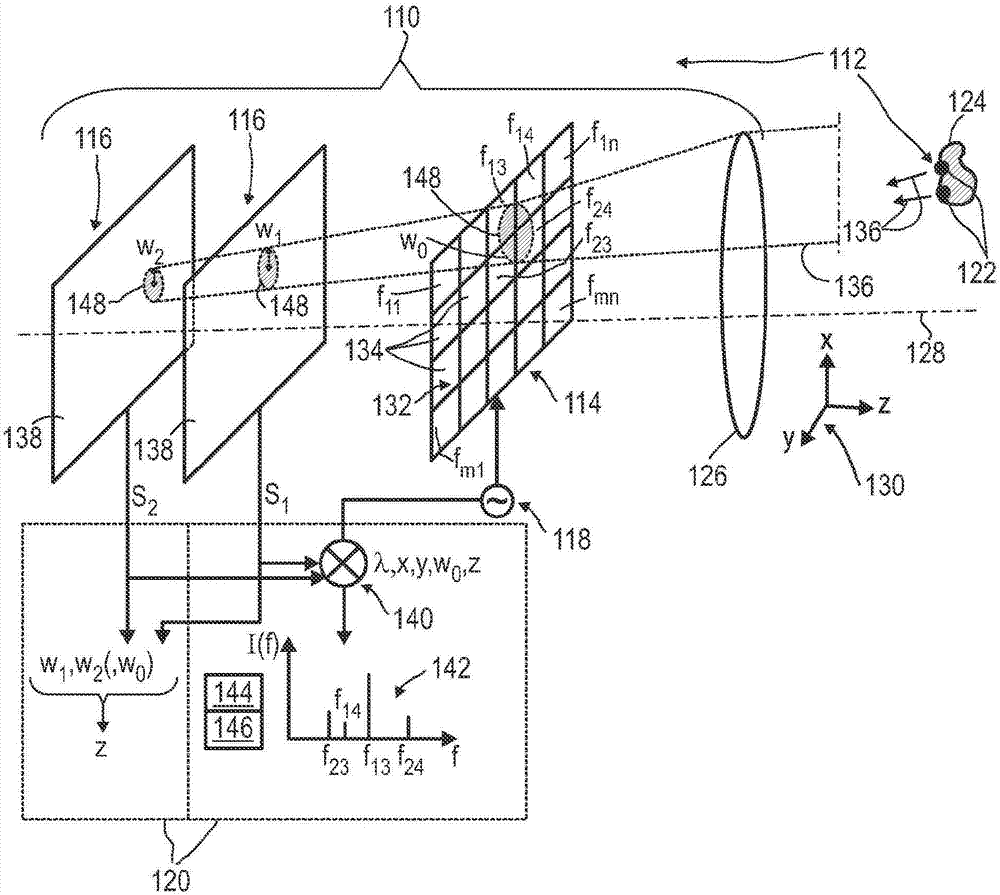
[0678] exist figure 1 In, an exemplary embodiment of an optical detector 110 and a detector system 112 is disclosed. The optical detector 110 comprises at least one spatial light modulator 114 , at least one optical sensor 116 , at least one modulator device 118 and at least one evaluation device 120 . In addition to at least the optical detector 110, the detector system 112 includes at least one beacon device 122 that is at least one of: attachable to an object 124, retainable by an object 124, and Can be integrated into object 124. In this embodiment, the optical detector 110 may also include one or more delivery devices 126, such as one or more lenses, preferably one or more camera lenses. exist figure 1 In the exemplary embodiment shown, spatial light modulator 114 , light sensor 116 and delivery device 126 are arranged in a stack along optical axis 128 . Optical axis 128 defines a longitudinal or z-axis, wherein a plane perpendicular to optical axis 128 defines an x-y...


PUM


Abstract

A method of controlling pixels (134) of at least one spatial light modulator (114) is disclosed. The spatial light modulator (114) has a matrix of pixels (132). Each pixel (134) is individually controllable. The method comprises the following steps: receiving at least one image (331),(342); defining at least one image segment (333) within the image (331),(344); assigning at least one gray scale value to each image segment (333),(348); assigning at least one pixel (134) of the matrix of pixels (132) to each image segment (333),(350); assigning a unique modulation frequency to each gray scale value assigned to the at least one image segment (333),(352); controlling the at least one pixel (134) of the matrix of pixels (132) assigned to the at least one image segment (333) with the unique modulation frequency assigned to the respective image segment (333),(354).

Description

technical field [0001] The present invention is based on US Provisional Application No. 61 / 867,180 of August 19, 2013 as e.g. , 61 / 906,430 of November 20, 2013 and 61 / 914,402 of December 11, 2013 and unpublished German Patent Application No. 10 2014 006 279.1 of March 6, 2014, European Patent Application of June 10, 2014 The general idea of ​​an optical detector as presented in Patent Application No. 14171759.5, International Patent Application No. PCT / EP2014 / 067466, August 15, 2014, US Patent Application No. 14 / 460,540, August 15, 2014, all of which The entire contents are incorporated herein by reference. [0002] The invention relates to a method of controlling the pixels of at least one spatial light modulator, an optical detection method, in particular for determining the position of at least one object, a modulator device, a modulator assembly, an optical detection detector and detector systems. The invention further relates to various uses of human-machine interfaces...

Claims


Application Information

Patent Timeline
Patent Type & Authority Applications(China)
IPC IPC(8): G06F3/042G01B11/25G01B11/14G01S17/42G01S7/481H04N25/00
CPCG01S7/4816G06F3/0304G01S3/781G01S5/16G01S17/46H04N23/74H04N25/00H04N23/84G01B11/14G01B11/25
Inventor R·森德I·布鲁德S·瓦鲁施S·伊尔勒E·蒂尔H·亨根
Owner BASF AG
Learn More