Optical detector

A technology of optical detector and optical sensor, applied in the field of optical detector

Inactive Publication Date: 2017-08-01
BASF AG
View PDF33 Cites 7 Cited by
  • Summary
  • Abstract
  • Description
  • Claims
  • Application Information

AI Technical Summary

Problems solved by technology

[0014] Despite the advantages implied by the devices and detectors described above, in particular by the detectors disclo

Method used


Image

  • Optical detector
  • Optical detector
  • Optical detector

Examples


Embodiment Construction

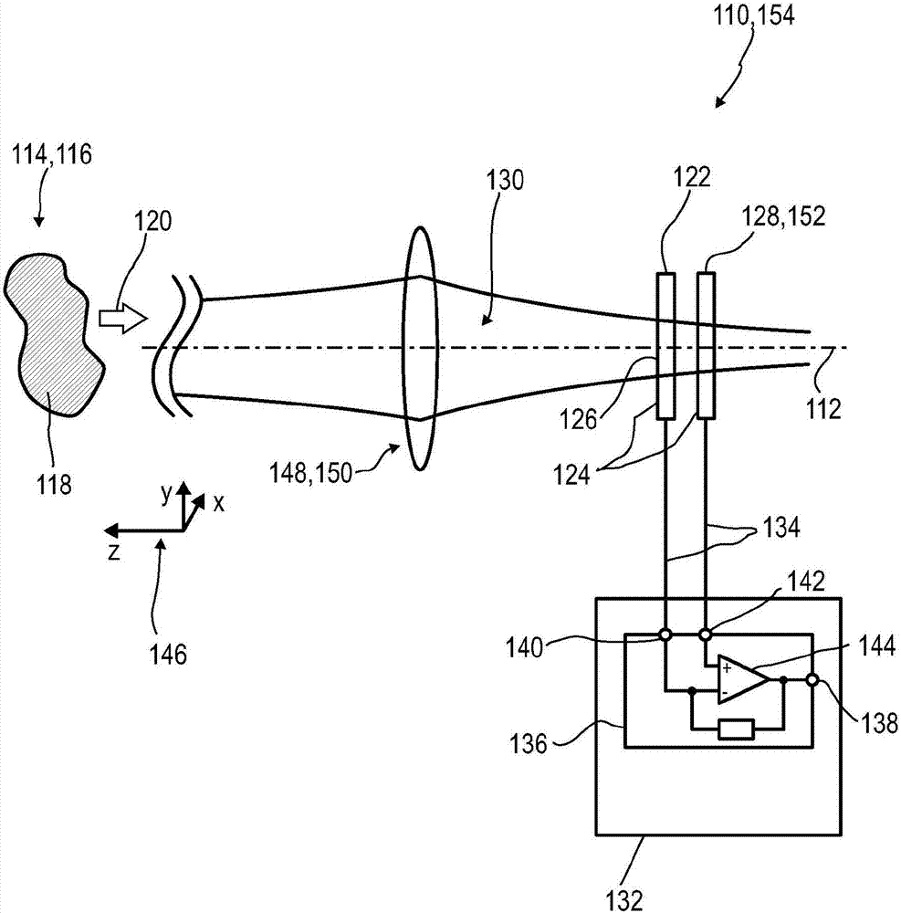
[0522] exist figure 1 , a first exemplary embodiment of an optical detector 110 according to the invention is shown in a highly schematic cross-sectional view in a plane parallel to the optical axis 112 of the optical detector 110 . The optical detector 110 may be used to detect a scene 114 or a portion thereof, wherein the scene 114 refers to a surrounding 116 of the optical detector 110 in which an image of the scene 114 or a portion thereof may be taken. At least one image of scene 114 or a portion thereof may comprise a single image or a progressive sequence of images, such as a video or video clip. In this particular example, the scene simply includes object 118 . Object 118 may be adapted to emit and / or reflect one or more light beams 120 towards optical detector 110 .

[0523] The optical detector 110 comprises at least one optical sensor 122 , which is embodied as a FiP sensor, ie because the optical sensor 122 has a sensor area 124 which can be illuminated by a ligh...


PUM


Abstract

An optical detector(110) is disclosed, comprising: at least one optical sensor(122) adapted to detect a light beam(120) and to generate at least one sensor signal, wherein the optical sensor(122) has at least one sensor region(124), wherein the sensor signal of the optical sensor(122) exhibits a non-linear dependency on an illumination of the sensor region(124) by the light beam (120) with respect to a total power of the illumination; at least one image sensor(128) being a pixelated sensor comprising a pixel matrix(174) of image pixels(176), wherein the image pixels(176) are adapted to detect the light beam(120) and to generate at least one image signal, wherein the image signal exhibits a linear dependency on the illumination of the image pixels(176) by the light beam(1,6) with respect to the total power of the illumination; and at least one evaluation device(132), the evaluation device(132) being adapted to evaluate the sensor signal and the image signal. In a particularly preferred embodiment, the non-linear dependency of the sensor signal on the total power of the illumination of the optical sensor(122) is expressible by a non-linear function comprising a linear part and a non-linear part, wherein the evaluation device(132) is adapted to determine the linear part and/or the non-linear part of the non-linear function by evaluating both the sensor signal and the image signal. Herein, the evaluation device(132), preferably, comprises a processing circuit(136) being adapted to provide a difference between the sensor signal and the image signal for determining the non-linear part of the non-linear function.

Description

technical field [0001] The invention is based on the general idea concerning optical detectors as proposed for example in WO 2012 / 110924 A1, US 2012 / 0206336 A1, WO 2014 / 097181 A1, US 2014 / 0291480 A1 or WO 2015 / 024871 A1, all of which The entire contents are incorporated herein by reference. [0002] The invention relates to an optical detector, a detector system and an optical detection method, in particular for determining the position of at least one object. The invention further relates to various uses of human-machine interfaces, entertainment devices, tracking systems, cameras and optical detectors for exchanging at least one item of information between a user and a machine. The devices, systems, methods and uses according to the invention can in particular be used, for example, in everyday life, games, traffic technology, production technology, safety technology, photography such as digital photography or artistic video photography, documentation or technical purposes, ...

Claims


Application Information

Patent Timeline
IPC IPC(8): G01C3/06G01S17/86
CPCG01C3/06G02B7/32G01S7/4816G01S17/46G01S5/16G01S11/12G01S17/86G01J1/08G01J1/4228G01J1/44
Inventor R·森德I·布鲁德S·瓦鲁施S·伊尔勒E·蒂尔
Owner BASF AG
Why Eureka
Try Eureka