
Ink fountain device

An ink fountain and ink fountain line technology, applied in decorative arts, painting tools, workshop equipment, etc., can solve the problems of shortened use time of the ink fountain, easy overflow of ink, small spool shaft, etc., and achieve easy operation, simple and reasonable structure, and reduced size. Effect

Inactive Publication Date: 2017-08-11
NANTONG INST OF TECH
View PDF11 Cites 2 Cited by
  • Summary
  • Abstract
  • Description
  • Claims
  • Application Information

AI Technical Summary

Problems solved by technology

[0002] The traditional ink fountain is large in size and inconvenient to use; the spool shaft is small, and it is laborious and time-consuming to crank it when taking up the thread; the ink container is open, and the ink is easy to dry. In addition, when the ink fountain is tilted, the ink is easy to Spill, both waste ink and pollute the site
[0003] There are some improved ink fountains on the market at present, but most of them only have a simple modification to the shape, and the size is still not ideal, and if the quality of the ink absorbing sponge is not ideal, it is not suitable for civil engineering construction with a large amount of use. It is still manual when taking up the thread, which is more troublesome; there is also a type of ink fountain that automatically takes up the thread, but the principle of its ink filling has not changed, and the size of the ink fountain is also larger, simply reducing the space for storing ink, which will inevitably make the use of the ink fountain Shorter times and frequent ink refills are also less than ideal

Method used


Image

  • Ink fountain device

Examples


Embodiment Construction

[0025] Preferred embodiments of the present invention will be described in detail below in conjunction with the accompanying drawings.

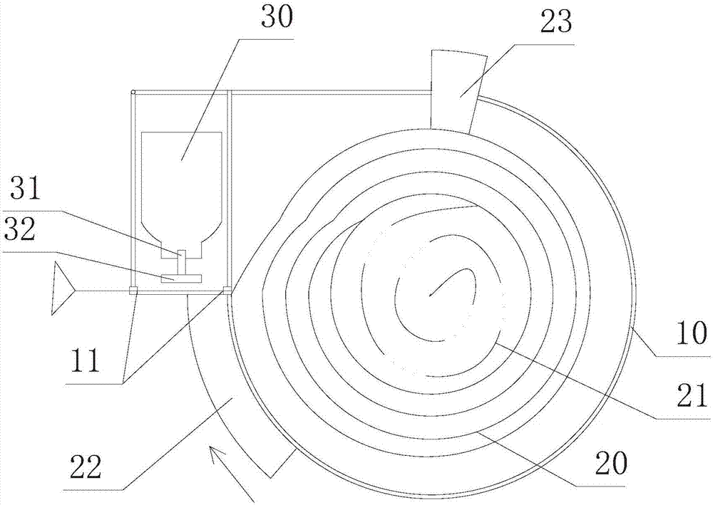
[0026] In order to achieve the purpose of the present invention, as figure 1 As shown, an ink fountain device is provided in one of the embodiments of the present invention, comprising:

[0027] The shell 10 is provided with a partition and is divided into an ink fountain line chamber and an ink chamber in the shell. A through hole is provided between the bottom of the partition and the shell, and the ink fountain line outlet is provided on the shell of the ink chamber. An ink fountain line channel is formed between the ink fountain line outlet and the through hole;

[0028] The ink mechanism includes an ink box 30 and a liquid outlet mechanism. The ink box is arranged in the ink chamber and above the ink fountain line channel, and the liquid outlet mechanism is connected and arranged at the bottom of the ink box;

[0029] The ink fountain ...


PUM


Abstract

The present invention discloses an ink fountain device. The ink fountain device comprises a housing, an ink mechanism and an ink fountain line mechanism. A partition plate is disposed inside the housing and divides the housing into an ink fountain line cavity and an ink cavity. The ink mechanism comprises an ink box and a liquid outlet mechanism. The ink fountain line mechanism comprises an ink fountain line, a spring, an ink fountain line self-locking assembly and an ink fountain line ink-soaking assembly, wherein a free end of the ink fountain line passes through an ink fountain line passage, the ink fountain line self-locking assembly is used for locking the ink fountain line inside the housing after the ink fountain line is pulled out of the housing, and the ink fountain line ink-soaking mechanism is used for pressing the ink fountain line against the liquid outlet mechanism so as to allow the ink fountain line to be soaked with ink. In the process of pulling the ink fountain line outwards, the ink fountain line ink-soaking mechanism presses the ink fountain line against the liquid outlet mechanism so as to allow the ink fountain line to be soaked with ink, the ink fountain line self-locking assembly locks the ink fountain line inside the housing after the ink fountain line is pulled out of the housing, the ink fountain line outside the housing is then tensioned to allow a worker to snap the ink fountain line, and automatic collection of the ink fountain line can be realized by the spring. Therefore, the ink fountain device is simple and reasonable in structure, small in size and convenient to operate.

Description

technical field [0001] The invention relates to an ink fountain device. Background technique [0002] The traditional ink fountain is large in size and inconvenient to use; the spool shaft is small, and it is laborious and time-consuming to crank it when taking up the thread; the ink container is open, and the ink is easy to dry. In addition, when the ink fountain is tilted, the ink is easy to Spill, not only waste ink but also pollute the site. [0003] There are some improved ink fountains on the market at present, but most of them only have a simple modification to the shape, and the size is still not ideal, and if the quality of the ink absorbing sponge is not ideal, it is not suitable for civil engineering construction with a large amount of use. It is still manual when taking up the thread, which is more troublesome; there is also a type of ink fountain that automatically takes up the thread, but the principle of its ink filling has not changed, and the size of the in...

Claims


Application Information

Patent Timeline
Patent Type & Authority Applications(China)
IPC IPC(8): B25H7/04B44D3/38
CPCB25H7/04B44D3/38
Inventor 范月波
Owner NANTONG INST OF TECH
Learn More