Beauty tool quick storage device

A storage device and beauty tool technology, applied in the beauty field, can solve the problems such as the inability to automatically rewind the power cord, the inability to quickly take out the beauty tools, the inability to quickly store the beauty tools, etc., to achieve easy separation, cleaning and foreign body removal operations, and save production investment. , The effect of saving the time of manual reeling

Inactive Publication Date: 2021-04-02
阜阳洁平日化有限公司
View PDF1 Cites 0 Cited by
  • Summary
  • Abstract
  • Description
  • Claims
  • Application Information

AI Technical Summary

Problems solved by technology

[0005] The purpose of the present invention is to address the deficiencies of the prior art, by arranging the installation mechanism to cooperate with the take-up mechanism, so that the installation mechanism can realize the automatic take-up and untwisting work of the take-up mechanism in the process of opening and closing, thereby solving the problem. It solves the technical problems that the power cord cannot be automatically rewound, that is, the beauty tools cannot be quickly stored, and the beauty tools cannot be quickly taken out, and then the automatic rewinding is realized, and the effect of convenient and quick use is achieved.

Method used


Image

  • Beauty tool quick storage device
  • Beauty tool quick storage device
  • Beauty tool quick storage device

Examples


Embodiment 1

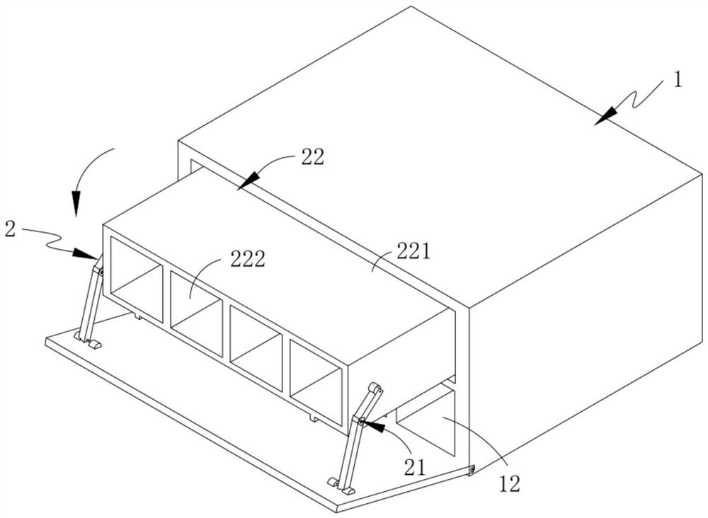
[0052] Such as figure 1 As shown, a quick storage device for beauty tools, including:

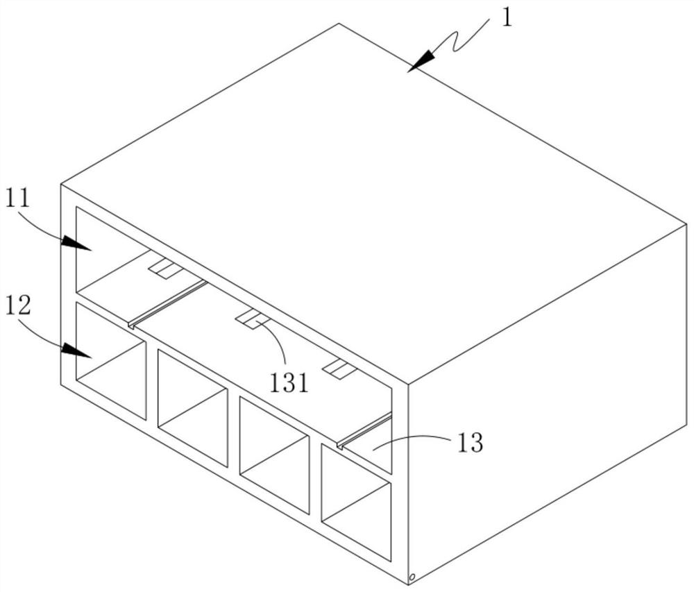
[0053] A box 1, the box 1 comprising an upper space 11, a lower space 12 disposed below the upper space 11, and a partition 13 for separating the upper space 11 and the lower space 12;

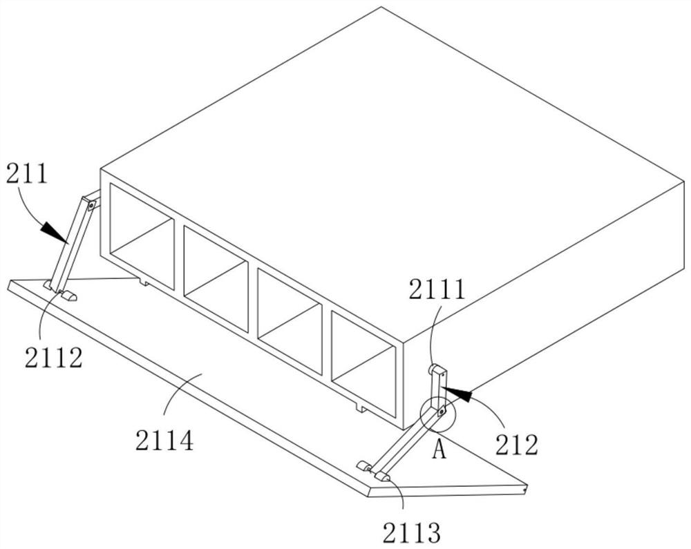
[0054] The installation mechanism 2, the installation mechanism 2 is slidably arranged above the partition 13, which includes a push-pull assembly 21 and a storage assembly 22 with one end connected to the push-pull assembly 21; and

[0055] The wire take-up mechanism 3 , the wire take-up mechanism 3 is arranged inside the lower space 12 , and it includes a drive assembly 31 with one end arranged on the box body 1 and a wire take-up assembly 32 sleeved on the drive assembly 31 .

[0056] In this embodiment, by setting the installation mechanism 2 to cooperate with the take-up mechanism 3, the installation mechanism 2 can realize the automatic take-up and untwisting work of the take-up mechanism 3 in the p...

Embodiment 2

[0085] Such as Figure 10 As shown, the components that are the same as or corresponding to those in the first embodiment are marked with the corresponding reference numerals in the first embodiment. For the sake of simplicity, only the differences from the first embodiment will be described below. The difference between this embodiment two and embodiment one is:

[0086] further, such as Figure 10 As shown, the fixing plate 3131 is located behind the wire slot a223 and has different forms of sockets 3132 on its surface.

[0087] In this embodiment, by arranging different types of jacks 3132, power cords with different plug specifications, such as two-hole plugs, three-hole plugs, four-hole plugs, and USB plugs, avoid single use, are widely used, and save equipment production investment. .

[0088] work process:

[0089] First open the sliding door 2114, under the traction of the sliding door 2114, the transmission rod 21151 drives the transmission rod 21152 to rotate, an...


PUM


Abstract

The invention relates to a beauty tool quick storage device. The beauty tool quick storage device comprises a box body, a mounting mechanism and a winding mechanism. The box body comprises upper-layerspace, lower-layer space arranged below the upper-layer space and a partition plate used for partitioning the upper-layer space and the lower-layer space. The mounting mechanism is arranged above thepartition plate in a sliding manner and comprises a push-pull assembly and a containing assembly with one end connected with the push-pull assembly. The winding mechanism is arranged in the lower-layer space and comprises a driving assembly and a winding assembly, one end of the driving assembly is arranged on the box body, and the winding assembly is arranged on the driving assembly in a sleeving manner. According to the beauty tool quick storage device, the technical problems that a power line cannot be automatically wound, that is, beauty tools cannot be rapidly stored, and beauty tools cannot be rapidly taken out are solved, and the effects of automatic winding and convenient and rapid use are achieved.

Description

technical field [0001] The invention relates to the field of beauty technology, in particular to a quick storage device for beauty tools. Background technique [0002] In the existing beauty tool storage box, the storage space provided on the storage box body for storing beauty tools is exposed to the outside, because this storage space not only needs to accommodate beauty tools, but also accommodates power cords; therefore, it will have a certain length. The power cord is folded into multiple sections for storage. If you find it inconvenient or troublesome, you often wrap the power cord around the beauty tool for careless storage. [0003] The patent document with the patent number CN103895963A discloses a beauty tool storage box, including: an outer box with a first storage part; a beauty tool with a power cord; stored in the first storage part of the outer box, and has and the inner box of the second storage part of the power cord; and the power supply part arranged on t...

Claims


Application Information

Patent Timeline
Patent Type & Authority Applications(China)
IPC IPC(8): B65G47/52B65G47/90
CPCB65H75/38B65H75/44
Inventor 郭长杰
Owner 阜阳洁平日化有限公司
Why Eureka
Try Eureka