
Apparatus and Method for Detecting Mura Defects

A defect and equipment technology, applied in the field of equipment for spot defect detection, can solve the problems of process efficiency degradation, inability to determine the type of spot defect, etc.

Active Publication Date: 2017-08-11
AP SYST INC
View PDF7 Cites 5 Cited by
  • Summary
  • Abstract
  • Description
  • Claims
  • Application Information

AI Technical Summary

Problems solved by technology

However, the spot defect detection device according to the related art may only detect the spot effect occurring on the surface of the display panel, but cannot determine the kind of the spot defect.
Therefore, it is difficult to find out what causes the spot defect, and when the process is delayed to find the cause, the efficiency of the process is degraded

Method used


Image

  • Apparatus and Method for Detecting Mura Defects
  • Apparatus and Method for Detecting Mura Defects
  • Apparatus and Method for Detecting Mura Defects

Examples


Embodiment Construction

[0027] Hereinafter, embodiments will be described in more detail with reference to the accompanying drawings. This disclosure may, however, take different forms and should not be construed as limited to the embodiments set forth herein. Rather, these embodiments are provided so that this disclosure will be thorough and complete, and will fully convey the scope of this disclosure to those skilled in the art. The drawings may be exaggerated in order to describe the present invention in detail, and in the drawings, like reference numerals refer to like elements.

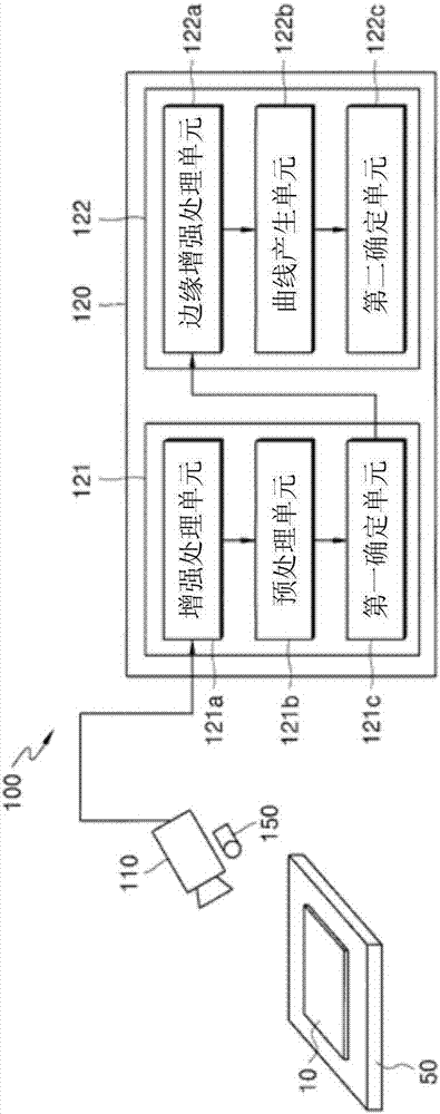
[0028] figure 1 A view illustrating a structure of an apparatus for detecting a spot defect according to an exemplary embodiment.

[0029] First, see figure 1 , the apparatus 100 for detecting spot defects according to an exemplary embodiment includes: a capture unit 110 for capturing an image of the display panel 10; and a processing unit connected to the capture unit 110 to detect images from the captured Image bl...


PUM


Abstract

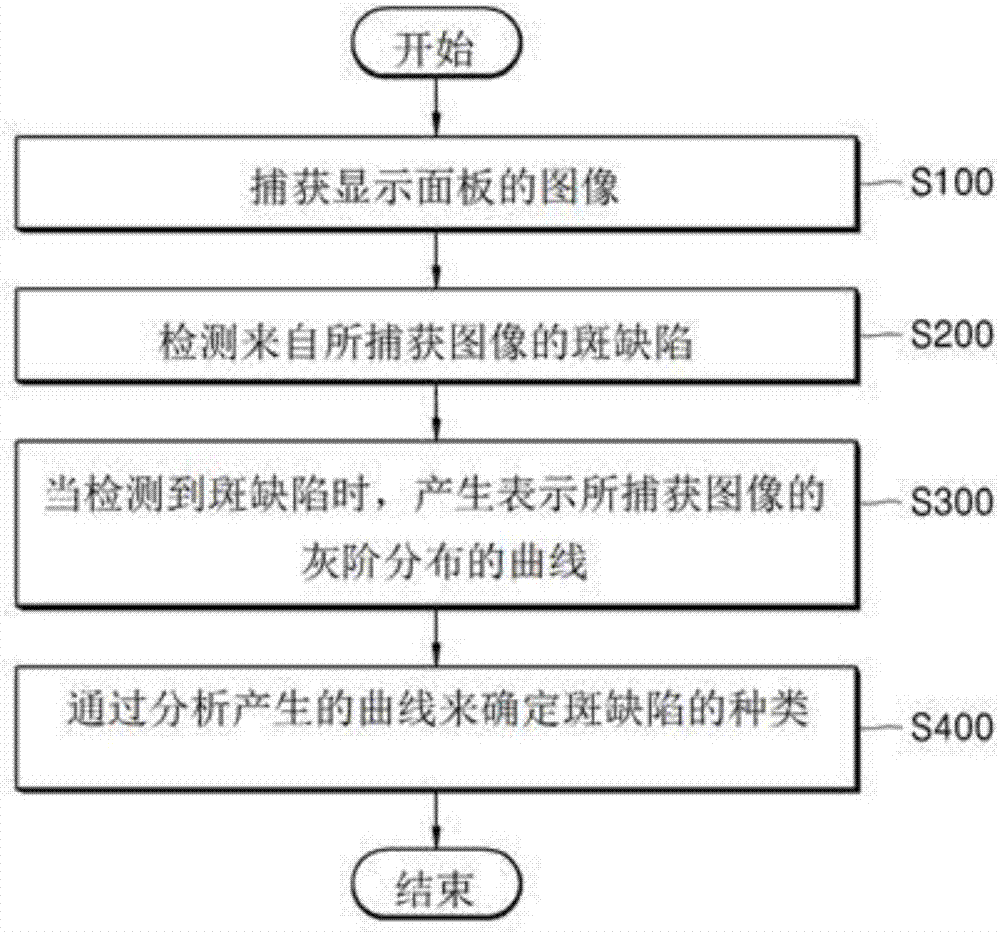
The invention discloses an apparatus and a method for detecting mura defects, and the method comprises the steps of obtaining image of a display panel; detecting the mura from the image; generating a curve for expressing image gray scale distribution when an mura defect is detected; and analyzing the cure to determine the category of the mura defect. According to the method, the mura defect on the display panel can be detected and the mura defect category can be determine.

Description

technical field [0001] The present disclosure relates to an apparatus and method for detecting a spot defect, and more particularly, to an apparatus and method for detecting a spot defect capable of detecting a spot defect of a display panel and determining a type of the spot defect. Background technique [0002] As the size of a display panel such as a liquid crystal display device becomes larger, it is difficult to ensure uniformity when performing an annealing process, and thus various alternatives have been proposed. One of the alternatives is an annealing method using a laser. [0003] That is, the laser beam output from the laser irradiator is passed through the quartz window to irradiate the display panel. This laser beam having a line shape irradiates the display panel in the shape of a curtain while being perpendicular or slightly inclined to the display panel. And, the entire surface of the display panel is irradiated with the laser beam, although the display pan...

Claims


Application Information

Patent Timeline
IPC IPC(8): G01N21/88
CPCG01N21/88
Inventor 赵相熙蒋盛旭元祥运
Owner AP SYST INC
Learn More