Protective cover and isolation switch equipped with same
What is AI technical title?
AI technical title is built by Patsnap AI team. It summarizes the technical point description of the patent document.
A technology of isolating switch and protective cover, which is applied in the field of protective cover and isolating switch with it, can solve the problems of low work efficiency and cumbersome operation steps, and achieve the effects of improving work efficiency, facilitating mold processing, and simplifying installation and removal steps
Inactive Publication Date: 2017-08-11
浙江金莱勒电气有限公司
View PDF8 Cites 3 Cited by
Summary
Abstract
Description
Claims
Application Information
AI Technical Summary
This helps you quickly interpret patents by identifying the three key elements:
Problems solved by technology
Method used
Benefits of technology
Problems solved by technology
[0004] The technical problem to be solved by the present invention is to overcome the technical defects that the fuse-type isolating switch in the prior art needs to disassemble the protective cover when connecting the incoming or outgoing cables, so that the operation steps are cumbersome and the work efficiency is low, thereby providing a When connecting the incoming or outgoing cables, it is not necessary to disassemble the incoming wires of the protective cover, so the operation steps are simple and the work efficiency is high.
Method used
Image
Click on the blue label to locate the original text in one second.
Reading with bidirectional positioning of images and text.
Examples
Embodiment 1
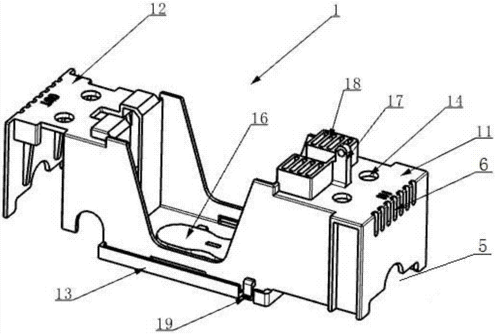
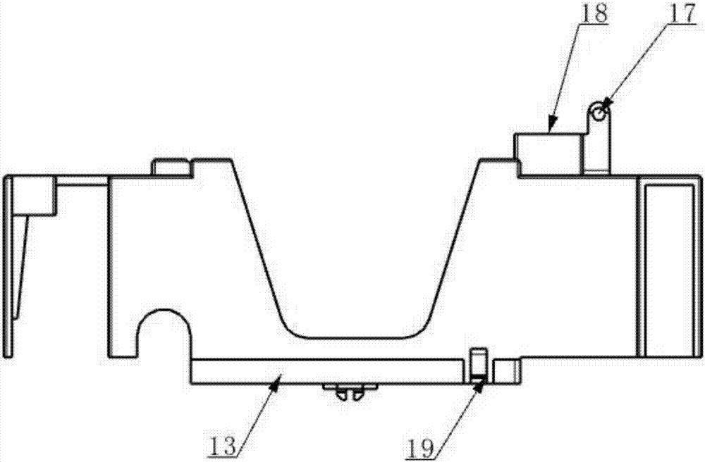
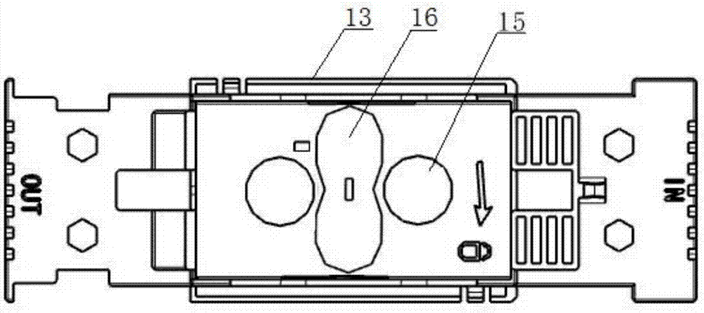
[0051] Such as figure 1 , figure 2 , image 3 , Figure 4 As shown, a protective cover includes a cover body 1 , a threading port 5 , a first operating port 14 , a connecting plate 13 , a second operating port 15 , a cover plate 16 , a latch 17 , a grille plate 18 and a cooling hole 6 .
[0052] The cover 1 includes a first cover 11 and a second cover 12, the first cover 11 is used to cover the incoming line contact seat 21 connected to the incoming line, and the second cover 12 is used to cover the outgoing line connected to the outgoing line Contact seat 22.
[0053] The threading opening 5 is arranged on the cover body 1 or between the cover body 1 and the base 2, and is used for passing incoming or outgoing wires.
[0054] The first operating port 14 is provided on the cover body 1 and is used for an operating tool to pass through to connect the incoming or outgoing wires to the contact base, or to disconnect the incoming or outgoing wires from the contact base.
[0...
Embodiment 2
[0070] Such as Figure 5 , Figure 6 , Figure 7 , Figure 8 , Figure 9 As shown, an isolating switch includes a base 2 , a protective cover and an upper cover 4 .
[0071] The base 2 is provided with a contact seat at both ends, and the contact seat has a power connection part 23 for cooperating with contact blades 31 at both ends of the fuse 3 and a wiring part 24 connected with an external incoming and outgoing cable.
[0072] The protective cover is the protective cover described in any solution in Embodiment 1, installed on the base 2, and used to cover the contact seat.
[0073] The upper cover 4 is arranged above the protective cover in an openable and closable manner, and has a cavity for accommodating and installing the fuse 3. One end has a pivot joint 41 for pivotally connecting with the base 2, and the other end has a pivoting portion 41 for connecting with the base 2. The socket part 42 to which the protective cover is plugged.
[0074] Instructions
[007...
PUM
Abstract
The invention provides a protective cover and an isolation switch equipped with the same, and belongs to the technical field of parts of an electric switch apparatus. The protective cover comprises a cover body, a threading port and a first operating port, wherein the cover body is suitable for being mounted on the base of the isolation switch and used for covering at least one contact base which is mounted on the base and used for connecting an inlet wire or an outlet wire; the threading port is formed in the cover body or between the cover body and the base, and used for allowing the inlet wire or the outlet wire to pass through; and the first operating port is formed in the cover body and used for allowing an operating tool to pass through to connect the inlet wire or the outlet wire on the contact base or remove the connection between the inlet wire and the contact base or between the outlet wire and the contact base. The protective cover provided by the invention is mounted on the base of the isolation switch, so that the contact base connected with the inlet wire or the outlet wire can be covered; and the first operating port is formed in the protective cover, the inlet wire or the outlet wire on the contact base can be connected and contacted without detaching the protective cover, so that wire connecting and wire detaching steps of the isolation switch can be simplified.
Description
technical field [0001] The invention relates to the technical field of components of an electric switchgear, in particular to a protective cover and an isolating switch having the same. Background technique [0002] The fuse-type isolating switch is a current protector. Its working principle is: when the current in the circuit exceeds the set value for a certain period of time, the heat generated by the current will melt the melt inside the isolating switch, thereby disconnecting the circuit. . The fuse type isolating switch mainly plays the role of isolation or short circuit protection in the line. When the isolating switch is in the separated position, the insulation distance between the moving and static contacts reaches a certain standard, and it has an obvious disconnection mark. When it is in the closed position, it can withstand the normal circuit current and the abnormal condition current within a certain period of time. [0003] Chinese patent document CN105374591...
Claims
Application Information
Patent Timeline
Application Date:The date an application was filed.
Publication Date:The date a patent or application was officially published.
First Publication Date:The earliest publication date of a patent with the same application number.
Issue Date:Publication date of the patent grant document.
PCT Entry Date:The Entry date of PCT National Phase.
Estimated Expiry Date:The statutory expiry date of a patent right according to the Patent Law, and it is the longest term of protection that the patent right can achieve without the termination of the patent right due to other reasons(Term extension factor has been taken into account ).
Invalid Date:Actual expiry date is based on effective date or publication date of legal transaction data of invalid patent.

