Perpendicular vibration road roller

A vertical vibration and road roller technology, applied in the field of road rollers, can solve the problems of consumption in the horizontal direction, incomplete action, and affecting the compaction effect, etc.

Inactive Publication Date: 2017-08-18
青岛科泰重工机械有限公司
View PDF4 Cites 2 Cited by
  • Summary
  • Abstract
  • Description
  • Claims
  • Application Information

AI Technical Summary

Problems solved by technology

[0004] The present invention proposes a vertical vibratory roller, which solves the problem in the prior art that the force of the ordinary circular vib...

Method used


Image

  • Perpendicular vibration road roller

Examples


Embodiment Construction

[0019] The following will clearly and completely describe the technical solutions in the embodiments of the present invention with reference to the accompanying drawings in the embodiments of the present invention. Obviously, the described embodiments are only some, not all, embodiments of the present invention. Based on the embodiments of the present invention, all other embodiments obtained by persons of ordinary skill in the art without creative efforts fall within the protection scope of the present invention.

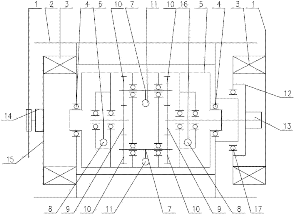
[0020] Such as figure 1 As shown, the vertical vibratory road roller includes a frame 1, and the frame 1 is provided with rollers 2 on both sides. device, the vertical vibration drive device is fixed on the vibration side connecting plate 13, and is connected to the frame 1 through a vibration damping block, the vertical vibration drive device is connected with a vibration device, and a walking drive device 14 is arranged between the frame 1, and on the frame 1 A ...


PUM


Abstract

The present invention proposes a vertical vibratory road roller, which includes a frame, rollers on both sides are arranged on the frame, a driving device is arranged between the rollers and the frame, and a driving device is arranged on the frame. Vertical vibration driving device, the vertical vibration driving device is connected with a vibration device, the invention can realize the vertical vibration of the steel wheel, reduce or even avoid the waste of pressure in the horizontal direction, improve the rolling efficiency and compaction quality, and realize energy saving.

Description

technical field [0001] The invention belongs to the technical field of road rollers, in particular to a vertical vibration road roller. Background technique [0002] At present, in recent years, with the continuous improvement of national infrastructure and the increase of large-scale projects, higher requirements have been placed on the compaction efficiency, compaction quality and environmental protection of vibratory rollers. The force of the ordinary circular vibratory road roller does not fully act on the compacted material, and part of the force is consumed in the horizontal direction, which affects the compaction effect. [0003] Therefore, there is an urgent need for a vertical vibratory road roller, which can realize the vertical vibration of the steel wheel, reduce or even avoid the waste of pressure in the horizontal direction, improve the road rolling efficiency and compaction quality, and realize energy saving. Contents of the invention [0004] The invention...

Claims


Application Information

Patent Timeline
IPC IPC(8): E01C19/28
CPCE01C19/282
Inventor 王继贤姚录廷王涛任胜利陈标高攀曲泓仲姚正博李正阳
Owner 青岛科泰重工机械有限公司
Why Eureka
Try Eureka