
Dual power contact drive mechanism

A driving mechanism and dual power supply technology, applied in the contact driving mechanism, emergency power supply arrangement, circuit and other directions, can solve the problems of shortening the service life of the switch, the speed is not fast enough, and the contacts are easily burnt out, so as to prolong the service life and avoid the burnout effect

Active Publication Date: 2020-01-17
KEDU ELECTRIC CO LTD
View PDF8 Cites 1 Cited by
  • Summary
  • Abstract
  • Description
  • Claims
  • Application Information

AI Technical Summary

Problems solved by technology

In the prior art, because the speed of the moving contact switching from one contact to another is not fast enough, the arc between the two contacts is not easy to break, especially because the voltage of the power supply is high and the current in the circuit is relatively large. It is easy to burn out the contacts, thereby shortening the service life of the switch

Method used


Image

  • Dual power contact drive mechanism
  • Dual power contact drive mechanism
  • Dual power contact drive mechanism

Examples


Embodiment Construction

[0034] The present invention will be described in detail below in conjunction with the embodiments and the accompanying drawings. It should be noted that the described embodiments are only intended to facilitate the understanding of the present invention, rather than limiting it in any way.

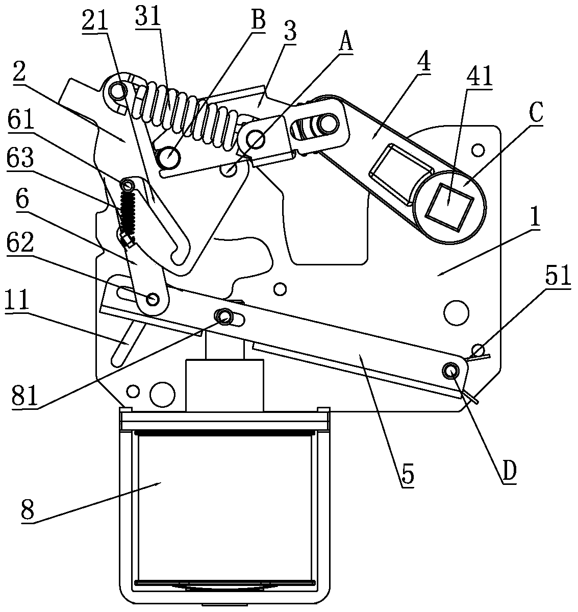
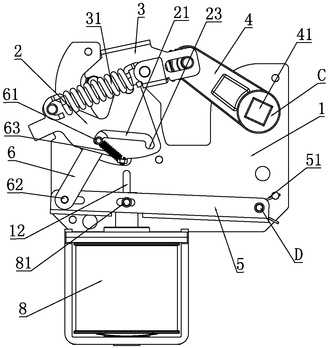
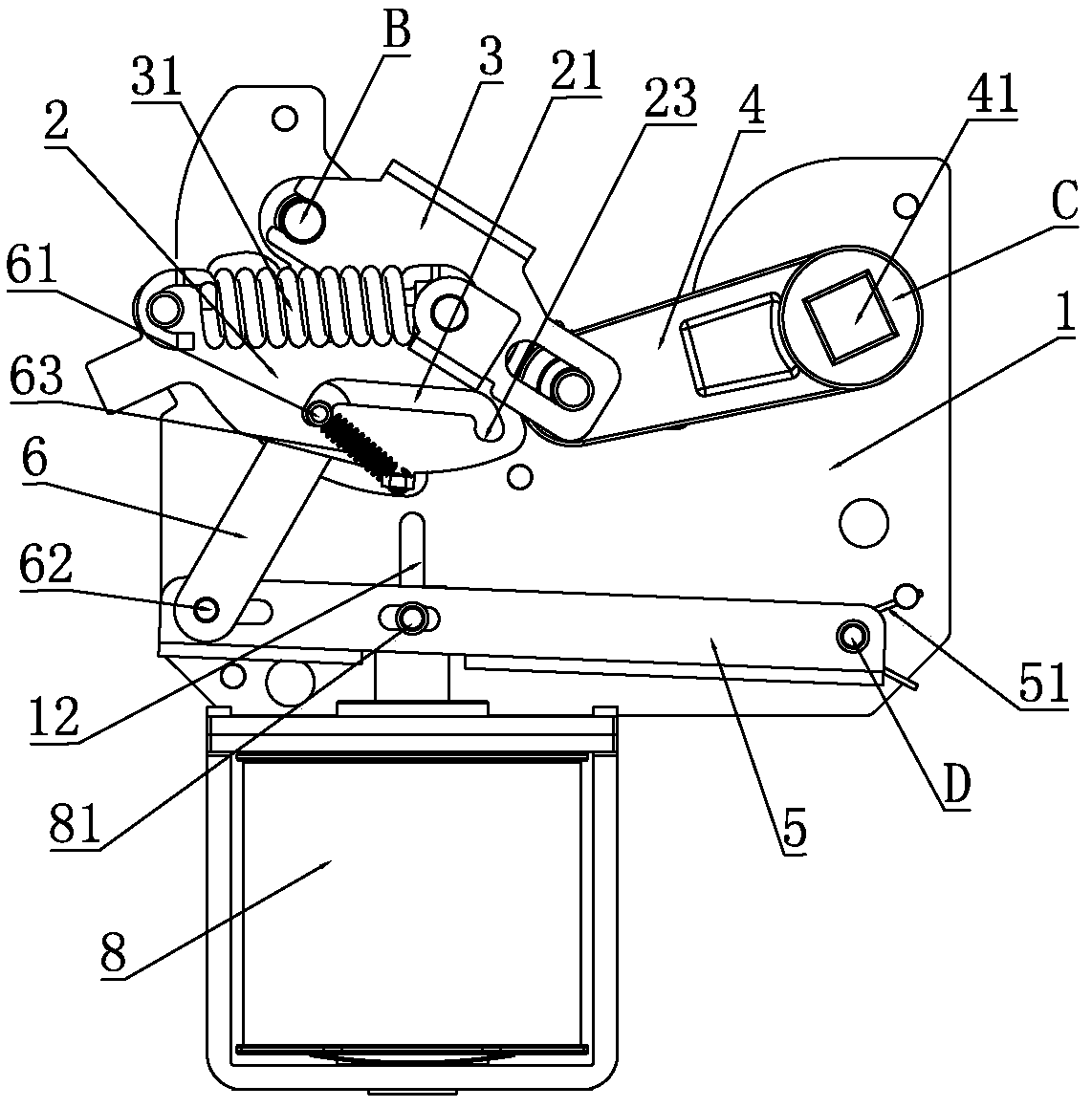
[0035] see figure 1 and Figure 7 As shown, a dual power contact driving mechanism provided in this embodiment has a structure including a fixed plate 1, a rotating shaft A of the movable frame 2, a rotating shaft B of the driving frame 3, a rotating shaft C of the moving contact frame 4 and a movable The rotation axes D of the rods 5 are all mounted on the fixed plate 1 . Also offer the first guide hole 11 and the second guide hole 12 on the fixed plate 1, the connecting rod 62 that slidably connects the left end of the movable rod 5 and the lower end of the connecting rod 6 is inserted in the first guide hole 11 and can be slid, slidably connected. The middle part of movable rod 5 and...


PUM


Abstract

The invention discloses a double-power-supply contact driving mechanism. The structure of the double-power-supply contact driving mechanism can be rotated through a driver driving a movable rack to rotate; when the movable rack begin rotating, the driving force of the movable rack drive for driving the driving rack to rotate to one direction can balance a resistance of the moving contact rack which blocks the driving rack from rotating to the direction; the driving rack and the moving contact rack stand still until the moving rack is rotated to a certain angle; when the driving force of the moving rack for driving the driving rack to rotate to one direction is not big enough to balance the resistance of the moving contact rack for preventing the driving rack from rotating to the direction, the driving rack is suddenly rotated to an opposite direction under the action of the driving force and the moving contact rack is suddenly rotated to the direction too under the action of the driving rack, which is a jump action of the driving rack and the moving contact rack. Because the jump action is very fast and switching of the moving contact can be fast completed between two static contacts, the arc between two contacts can be snapped, which can effectively prevent burning of the contacts so as to prolong the service life.

Description

technical field [0001] The invention relates to the technical field of a dual-power switch, in particular to a dual-power contact drive mechanism. Background technique [0002] The dual power supply switch is a switch that automatically switches to another power supply due to a power failure. For example, after the first power supply fails, the switch automatically switches to the second power supply to supply power to the load. It is widely suitable for UPS-UPS, UPS-generator, UPS-mains, mains-mains and other two-way power supply continuous power conversion. [0003] The dual power supply switch drives the movement of the moving contact through the driving mechanism, so that the moving contact can switch back and forth between the two contacts, thereby realizing the power supply switching between the two power sources. In the prior art, because the speed of the moving contact switching from one contact to another is not fast enough, the arc between the two contacts is not ...

Claims


Application Information

Patent Timeline
Patent Type & Authority Patents(China)
IPC IPC(8): H01H3/28H01H3/32H01H5/14H02J9/06
CPCH01H3/28H01H3/32H01H5/14H02J9/06
Inventor 郑春开李子平廖军
Owner KEDU ELECTRIC CO LTD
Learn More