LED (light-emitting diode) drive control circuit

A technology of LED driving and current sampling, applied in energy-saving control technology, lamp circuit layout, electric light source, etc., can solve the problem of damaging LED loads and power tubes, and achieve the effect of avoiding burnout

Active Publication Date: 2011-08-03
HANGZHOU SILAN MICROELECTRONICS
View PDF3 Cites 18 Cited by
  • Summary
  • Abstract
  • Description
  • Claims
  • Application Information

AI Technical Summary

Problems solved by technology

[0013] After the above-mentioned LED drive circuit is opened, when the LED load is open for a period of time, the voltage of the comparison port COMP continues to rise, and the waveform diagram is as follows image 3 As shown, if the LED load is turned on, especially when the input voltage VIN is high, the external inductor current will suddenly rise to a high level until the LED drive circuit loop is adjusted to a stable value, and the instantaneous high inductor current may damage the LED load and power tube

Method used


Image

  • LED (light-emitting diode) drive control circuit
  • LED (light-emitting diode) drive control circuit
  • LED (light-emitting diode) drive control circuit

Examples


Embodiment Construction

[0038] The content of the present invention will be described in detail below in conjunction with the block diagram of the present invention and the schematic diagrams of specific embodiments.

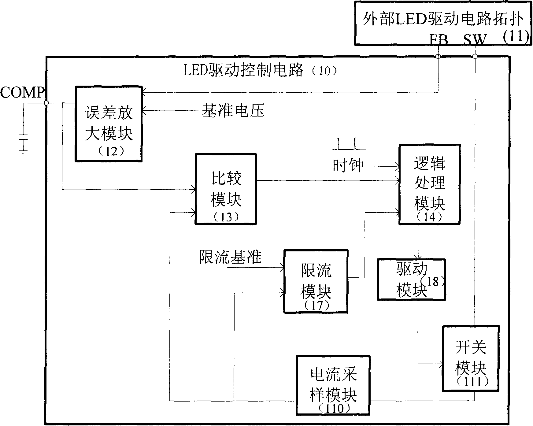
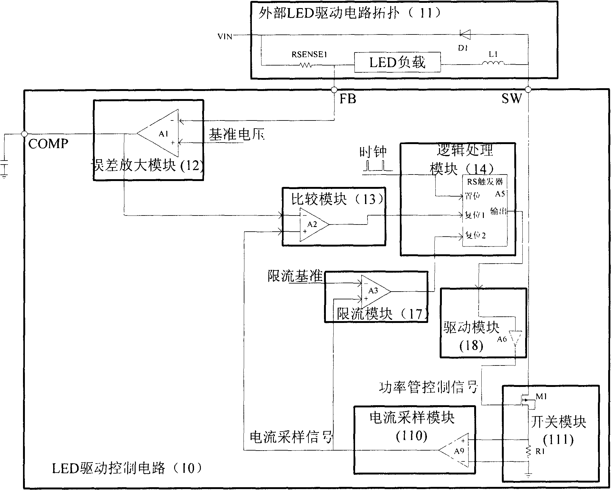
[0039] Such as Figure 4 As shown, the LED drive control circuit 21 includes:

[0040] LED load sampling port FB, switch port SW, comparison port COMP;

[0041] Error amplification module 22: the error amplification module 22 inputs the LED load sampling voltage through the LED load sampling port, and compares and amplifies the LED load sampling voltage with the reference voltage;

[0042] Current sampling module 210: the current sampling module 210 samples the current flowing through the power tube in the switch module 211, and the output current sampling signal is provided to the comparison module 23 and the current limiting module 27;

[0043] A comparison module 23, the comparison module 23 compares the voltage of the comparison port COMP with the current sampling signal output b...


PUM


Abstract

The invention discloses a LED (light-emitting diode) drive control circuit, which comprises an LED load sampling port, a switch port and a comparison port. An error amplifier module compares the LED load sampling voltage with the reference voltage and amplifies the LED load sampling voltage; a comparison module feeds the voltage of the comparison port and the current sampling signal to a logic processing module after comparing the voltage of the comparison port and the current sampling signal are compared; an open circuit detection protection module detects whether a LED load is open-circuited, detects the duration of the open circuit and outputs the open circuit status signal, an output for a first output end of the open circuit detection protection module and an output of the error amplifier module commonly control the voltage of the comparison port, and a second output end of the open circuit detection protection module outputs the current limiting threshold; a current limiting module feeds the current limiting threshold and the current sampling signal to the logic processing module after the current limiting threshold and the current sampling signal are compared; the logic processing module processes the logic of an input, and the output controls the switch of a power tube through a drive module. The LED drive control circuit prevents the current of an inductor of the LED drive circuit from rapidly rising and avoids the LED load and the power tube being burnt after the LED load is switched on.

Description

technical field [0001] The invention relates to an LED drive control technology, in particular to an LED load open circuit protection technology for an LED drive circuit in a fixed switching frequency step-down mode. Background technique [0002] At present, LED drive circuits can be divided into boost mode and buck mode according to different peripheral topologies, and can be divided into fixed switching frequency and variable switching frequency according to whether the switching frequency changes. Generally, in the LED drive control circuit using boost mode, the designer will take load open circuit protection to prevent the output voltage from getting out of control. However, in the general step-down mode LED drive circuit, especially in the high-power LED drive circuit, the LED drive control circuit with fixed switching frequency step-down mode is widely used. After the load is opened, no detection action is taken inside the chip, such as figure 1 The shown LED drive co...

Claims


Application Information

Patent Timeline
Patent Type & Authority Applications(China)
IPC IPC(8): H05B37/02
CPCY02B20/42Y02B20/40
Inventor 姚丰王栋吴建兴
Owner HANGZHOU SILAN MICROELECTRONICS
Why Eureka
Try Eureka