
Network roaming switching method and device

A switching device and network technology, applied in the field of communication, can solve the problems of data packet loss, the client cannot accept data, and the communication quality cannot be guaranteed, and achieves the effect of zero delay, guaranteed communication quality, and fast switching.

Active Publication Date: 2019-12-03
CHENGDU SKSPRUCE TECH
View PDF3 Cites 0 Cited by
  • Summary
  • Abstract
  • Description
  • Claims
  • Application Information

AI Technical Summary

Problems solved by technology

[0005] When the signal strength of the current communication AP is lower than the roaming switching threshold, it cannot guarantee that the signal strength of other associated APs is better than the current communication AP, and the communication quality after switching cannot be guaranteed.
[0006] When roaming from one AP to another, the client cannot accept the data sent by the AP due to the interruption of wireless service communication, and the problem of data packet loss occurs

Method used


Image

  • Network roaming switching method and device
  • Network roaming switching method and device
  • Network roaming switching method and device

Examples


no. 1 example

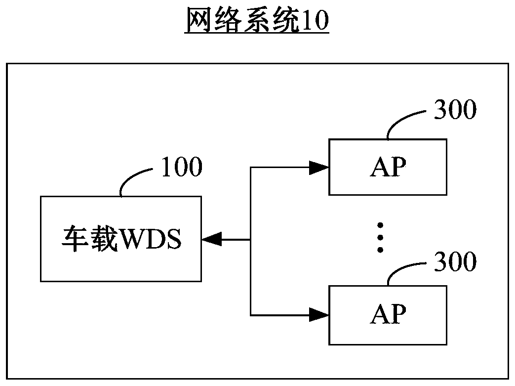
[0039] In the expressway wireless network, the roadside access wireless device AP300 can use double-sided directional outdoor high-power wireless devices, and one AP300 can be arranged every two kilometers. The vehicle-mounted WDS100 (wireless network bridge) is associated with the roadside access wireless device AP300, enabling the vehicle to realize data return while driving at a maximum speed of 150 km / h. In order to realize the fast roaming between the car and the roadside AP300 under such high-speed operation, and ensure the link communication quality, the present invention provides a network roaming switching method.

[0040] This solution uses network virtualization technology to realize fast switching of roaming, and can still accept the data sent by the original AP300 during the switching process, so as to realize zero delay and zero packet loss of the vehicle-mounted WDS100 uploading service data messages.

[0041] This solution uses network virtualization technology...

no. 2 example

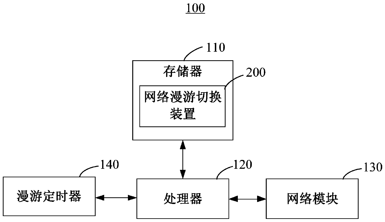
[0084] Please refer to Figure 8 , Figure 8 The functional module block diagram of the network roaming switching device 200 provided for the preferred embodiment of the invention. The network roaming switching device 200 is applied to a vehicle-mounted WDS 100 communicatively connected to multiple APs 300 arranged beside roads, and the device includes: a receiving sorting module 220 and a roaming detection module 230 .

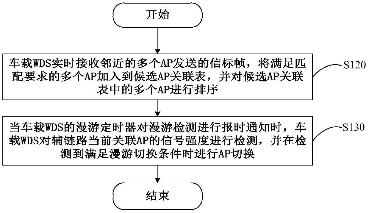
[0085] The receiving sorting module 220 is configured to receive beacon frames sent by multiple adjacent AP300s in real time, add multiple AP300s that meet the matching requirements to the candidate AP association table, and sort the multiple AP300s in the candidate AP association table .

[0086] In this embodiment, the receiving sorting module 220 is used to execute image 3 In step S120, for a specific description of the receiving sorting module 220, reference may be made to the description of step S120.

[0087] The roaming detection module 230 is con...


PUM


Abstract

The present invention provides a network roaming switching method and device. The network roaming switching method is applied to a vehicle-mounted WDS which is in communication connection with a plurality of AP arranged by the side of a road, and comprises the steps of using the vehicle-mounted WDS to real-timely receive the beacon frames sent by the plurality of adjacent AP, adding the plurality of AP satisfying a matching requirement in a candidate AP correlation table, and ranking the plurality of AP in the candidate AP correlation table. When a roaming timer of the vehicle-mounted WDS tells time to the roaming detection, the vehicle-mounted WDS detects the signal intensity of the auxiliary link currently correlated AP, and switches the AP when the situation that a roaming switching condition is satisfied is detected, so that the AP roaming rapid switching is realized, the communication quality after switching is guaranteed, at the same time, the zero time delay and the zero-packet-loss that the WDS uploads the service data messages are realized.

Description

technical field [0001] The present invention relates to the technical field of communications, and in particular, to a network roaming switching method and device. Background technique [0002] Network switching is usually similar to hard switching in cellular networks, that is, switching after disconnection. The client first disconnects the physical connection with the previous AP, and then establishes an association with the new AP. Because there is a process of disconnection and reconnection, the time delay of network switching will be more than 1 second, and in this process, the wireless service communication is interrupted, and the client cannot accept the data sent by the AP. [0003] In the prior art, the above-mentioned problem can be solved by adding a handover preparation action during the communication process between the client and the AP, that is, after finding a connectable AP, establish association with the AP in advance. Once the signal strength of the commu...

Claims


Application Information

Patent Timeline
Patent Type & Authority Patents(China)
IPC IPC(8): H04W36/00H04W36/08H04W36/30
CPCH04W36/0083H04W36/08H04W36/30
Inventor 赵义平李君徐力韵
Owner CHENGDU SKSPRUCE TECH
Learn More