Luggage carrier
A carrier and luggage technology, applied in the field of luggage carts, can solve problems such as unfavorable storage, increase user burden, and accelerate user fatigue, so as to achieve the effect of conveniently dragging luggage and improving convenience
- Summary
- Abstract
- Description
- Claims
- Application Information
AI Technical Summary
Problems solved by technology
Method used
Image
Examples
Embodiment 1
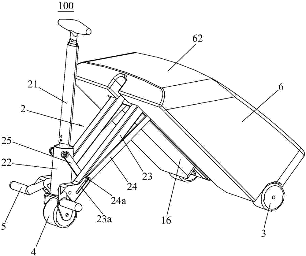
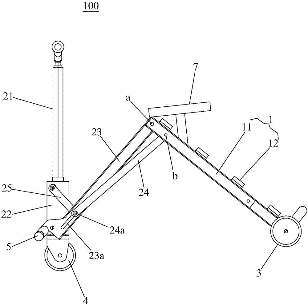
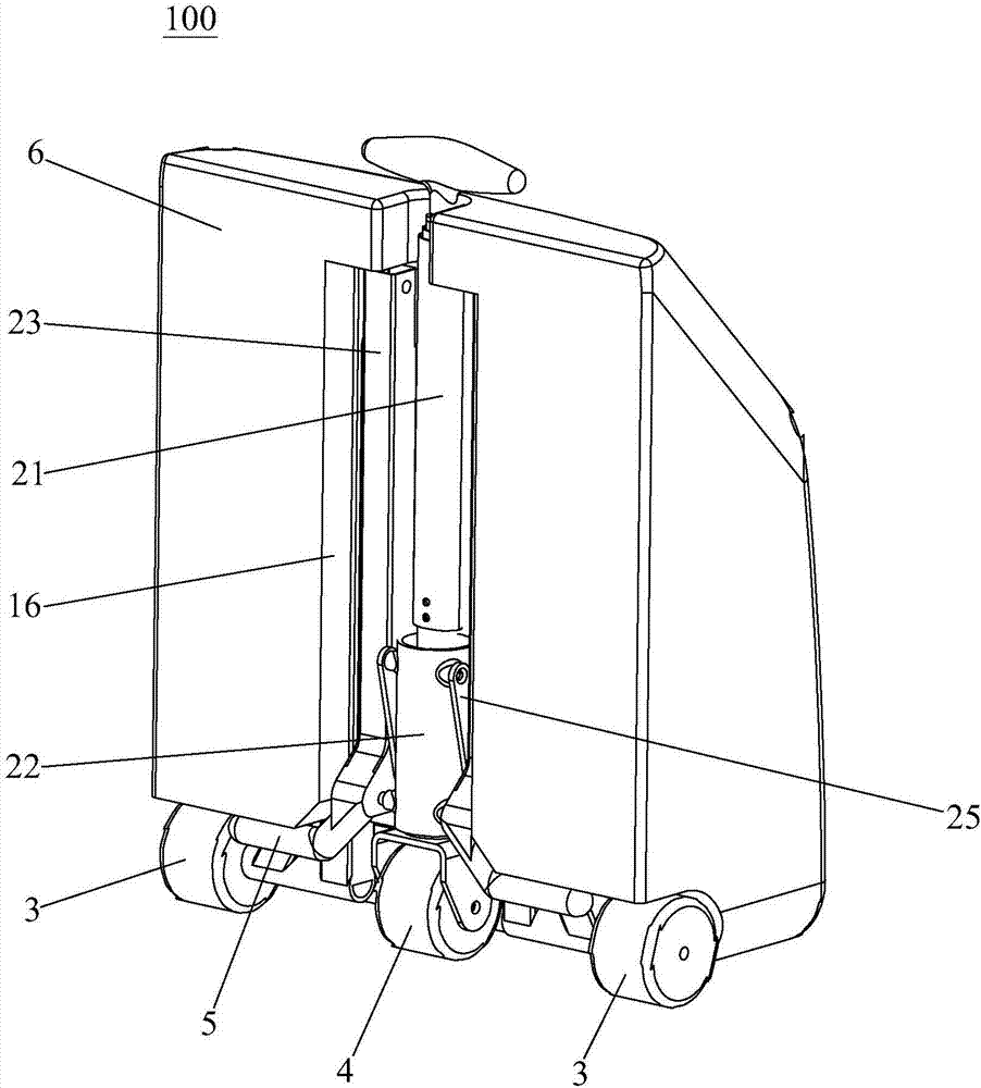
[0025] Such as figure 1 , figure 2 As shown, the luggage carrier 100 of the present invention includes a luggage rack 1 and a carrier rack 2. The luggage rack 1 is composed of two bottom bars 11 and a plurality of cross bars 12. The rear ends of the bottom bars 11 are provided with rear wheels 3. The front end of the carrier frame 2 is provided with a front wheel 4, and the carrier frame 2 includes a direction bar 21, a sleeve 22, and a main rod 23, a pull rod 24 and a pull rod 24 that are symmetrically arranged on both sides of the carrier frame 2. Linkage rod 25, the rear end of the main rod 23 is pivotally connected to the front end of the luggage rack 1 to form a pivot point a, the rear end of the pull rod 24 is pivotally connected to the luggage rack 1 to form a pivot point b, and the pivot point b Located near the front end of the luggage rack, the main rod 23 and the tie rod 24 are located inside the bottom rod 11; the front side wall of the main rod 23 is provided wi...
Embodiment 2
[0034] Such as Figure 4 and Figure 5As shown, the luggage rack 1, the direction bar 21, the sleeve 22 and other basic structures of the luggage carrier 200 in the second embodiment of the present invention are basically the same as the luggage carrier 100 in the first embodiment, the difference lies in the structure of the carrier rack 2 Above, the main rod 23 of this embodiment is provided with a first elongated hole 23a and a second elongated hole 23b, the first elongated hole 23a is close to the rear end of the main rod 23, and the second elongated hole The hole 23b is close to the front end of the main rod 23, the rear end of the pull rod 24 is pivotally connected to the luggage rack 1, the pivot point b is located at the rear end of the luggage rack 1, and the front end of the pull rod 24 passes through the first A shaft pin 24a is slidably disposed in the first elongated hole 23a. One end of the linkage rod 25 is pivotally connected to the upper end of the sleeve 22,...
PUM
 Abstract
Description
Claims
Application Information
 - R&D
- Intellectual Property
- Life Sciences
- Materials
- Tech Scout
- Unparalleled Data Quality
- Higher Quality Content
- 60% Fewer Hallucinations
Browse by: Latest US Patents, China's latest patents, Technical Efficacy Thesaurus, Application Domain, Technology Topic, Popular Technical Reports.
© 2025 PatSnap. All rights reserved.Legal|Privacy policy|Modern Slavery Act Transparency Statement|Sitemap|About US| Contact US: help@patsnap.com


