

Mechanical cabbage harvester
A technology of mechanical harvesting and cabbage, applied to agricultural machinery and implements, harvesters, applications, etc., can solve problems such as labor-intensive, unsafe, and vulnerable
Pending Publication Date: 2017-09-01
王建生
View PDF0 Cites 0 Cited by
- Summary
- Abstract
- Description
- Claims
- Application Information
AI Technical Summary
Problems solved by technology
However, most of them are harvested manually, which is labor-intensive, and when harvesting, it is easy to be injured and unsafe
Method used
View moreImage
Smart ImageViewing Examples

Examples
Embodiment
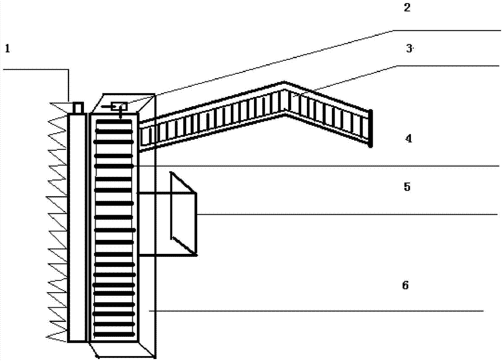
[0013] When adopting the above-mentioned cabbage mechanical harvester, earlier the cabbage mechanical harvester is articulated on the power traction machinery (four-wheel machine or walking tractor head position), and the adjustment is suitable for height. Then start the power equipment (four-wheel machine) to drive the reducer of the cabbage harvesting equipment to move, the lower cutting section of the header moves, grinds with the upper cutting piece, the cabbage is cut off immediately, enters the blocking frame, and then transports the cabbage through the header conveyor belt to the mouth of the box conveyor belt, and then transported to the four-wheel box bucket by the box conveyor belt for transport.
Login to View More PUM
 Abstract
The invention relates to a mechanical cabbage harvester which comprises shear clips, a speed reducer, a box transmission belt, a header transmission belt, a fixed bracket and a barrier frame. The shear clips are the shear clips (the shear clips in the upper row are fixed and the shear clips in the lower row move left and right) mounted in upper and lower rows of the front end of the head; the speed reducer is equipment fixed on one side of the header to provide power vertically in two directions; the box transmission belt is transportation equipment which is mounted on the rear side of the header and transmits harvested cabbages to a back box hopper; the header transmission belt is transportation equipment which transmits the harvested cabbage to an opening of the box transmission belt; the fixed bracket is a buckle for connecting power mechanical traction; the barrier frame is metal plates which encircle the three edges of the header to prevent cabbages from falling onto the ground. The design integrates harvesting and casing by means of mechanical traction. The cabbage mechanical harvester can be also used for harvesting kales and is safe and convenient and safe and labor-saving.
Description
technical field [0001] The invention relates to a vegetable harvester, in particular to a cabbage mechanical harvester tool. Background technique [0002] At present, cabbage planting is widely distributed in my country, and the planting area is large. However, most of them are harvested manually, which is labor-intensive, and when harvesting, it is easy to be injured and unsafe. Contents of the invention [0003] The technical problem to be solved by the invention is to provide a fast and safe mechanical harvester tool for cabbage. [0004] In order to solve the above problems, a convenient and practical mechanical harvesting device for cabbage according to the present invention is provided. It is characterized in that it is composed of a cutting piece 1, a reducer 2, a box transmission belt 3, a header transmission belt 4, a fixed bracket 5 and a blocking frame 6. Described clip 1 refers to two rows of clips up and down installed on the header front end (the top clip ...
Claims
Login to View More Application Information
Patent Timeline
 Patent Type & Authority Applications(China)
IPC IPC(8): A01D45/26
CPCA01D45/266
Inventor 王建生
Owner 王建生