Con-focal laser measuring method

A laser measurement and confocal technology, applied in the direction of measuring devices, optical devices, instruments, etc., can solve the problems of inconsistency and achieve the effect of measuring data

Active Publication Date: 2017-09-08
成都新成量工具有限公司
View PDF6 Cites 1 Cited by
  • Summary
  • Abstract
  • Description
  • Claims
  • Application Information

AI Technical Summary

Problems solved by technology

Therefore, it is impossible to unify when measuring and tracing the source with a ball probe

Method used


Image

  • Con-focal laser measuring method
  • Con-focal laser measuring method
  • Con-focal laser measuring method

Examples


Embodiment Construction

[0028] The present invention will be further described below in conjunction with accompanying drawing:

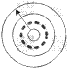
[0029] A confocal laser measurement method, the light beam is measured from the inside to the outside along the radius of the contact surface of the ball head, and is measured according to the step length of concentric circles with different radii, such as figure 1 As shown, a set of data is obtained: (x, y, depth), and a three-dimensional simulation diagram is drawn.

[0030] Further, the light beam is measured from the inside to the outside along the radius of the contact surface of the ball head, and is measured according to concentric circles with different radii to obtain a set of data: (x, y, depth) The specific operation steps are:

[0031] S1. Set the range of concentric circle radius r to [0, r], the origin coordinates (x, y) to (0, 0), and the sampling step to step;

[0032] S2. Calculating all the sampling radius lists radius;

[0033] S3. Add the origin to the...


PUM


Abstract

The invention discloses a con-focal laser measuring method. In the method, light beams are measured in equal step length along the ball head contact surface radius from the inner to the outer and according to the concentric circles of different radiuses. In this way, a group of data are obtained: (x,y, depth). Then, a three-dimensional simulation graph is drawn. According to the invention, through the use of the con-focal point to simulate the shape of a measuring ball head and through the adoption of ball surface contour line layered scanning method, a shape consistent with the standard measuring ball head can be formed to measure the surface of a workpiece so as to develop a measuring contact face completely consistent with the standard measuring ball head. The measuring method of the invention can be applied to a non-smooth surface and realizes consistency of measured data under the standards of baseline traceability.

Description

technical field [0001] The invention relates to the technical field of confocal laser measurement, in particular to a confocal laser measurement method. Background technique [0002] The existing confocal technology can only be applied to smooth surfaces, and when the measurement data is applied on a non-smooth surface, the data is not equal when compared with the traceable reference statically, so it brings reference traceability errors. The main reason is the influence of the roughness of the non-smooth surface. The diameter of the spot is too small, while the reference ball head is large. When the surface is not smooth, the data of the two forms a difference. The traditional probe is a ball head, usually ranging from 0.5-3mm. The contact surface is much larger than the confocal light spot during measurement. When measuring on a non-smooth surface, since the contact point of the ball head is a collection of surface peaks, the confocal The measurement spot is at U level, a...

Claims


Application Information

Patent Timeline
Patent Type & Authority Applications(China)
IPC IPC(8): G01B11/00
Inventor 张晓岗吕守涛李凯谢永强
Owner 成都新成量工具有限公司
Why Eureka
Try Eureka